Hi
I am back with another n00b question

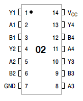
I want to reproduce a 3-in-1 cartridge which is mapper 205 :


Does anyone have any schematic for it?
Is it possible to find out schematic from mapper 205 and mapper 4 docs?
Mapper 205 information
Mapper 4 information
I'm confused why you would want to reproduce a $3 famicom cart that is still avalible in abundance?

It's what he does, and he's
extremely good at it
Perhaps this guy will be replicating our MMC3 games one day.
From what I gathered, Farrid like doing crazy project that no one else understand for the sake of learning and also for his ultimate project of a kunio kun MMC3 multicart.
As for recreating the multicart, it would be easier to replicate a cart that you have so you can study it or at least have a PCB picture of the cart. I think that recreating a cart with an obscure pirate mapper like that will be hard by just looking at the mapper documention...
I think FARID is trying to create an Iranian NES clone and corner the market. I say more power to you brother! Spread the Good Word of the 6502 and all her derivatives! Let the huddled masses feel the warm glow of Nintendo!
Or something...
Quote:
I'm confused why you would want to reproduce a $3 famicom cart that is still avalible in abundance?
Can you provide me a shot from its PCB?
I have a Master Fighter II (Mapper 189) :


 Mapper 189 information
Is it possible to convert it to Mapper 205?
Mapper conversion is something very hard to achieve from what I know and I wouldn't look in that direction to achieve your goal.
I think if you want a good NES Street Fighter II clone, rip the graphics from the pirate games, and throw out and rewrite all their code. Most pirate games are crap.
Occasionally you'll see some decently programmed pirate games, like Aladdin by
Hummer Team, or Super Aladdin by
Super Game. They put the licenced version of Aladdin (from NMS software) to shame.
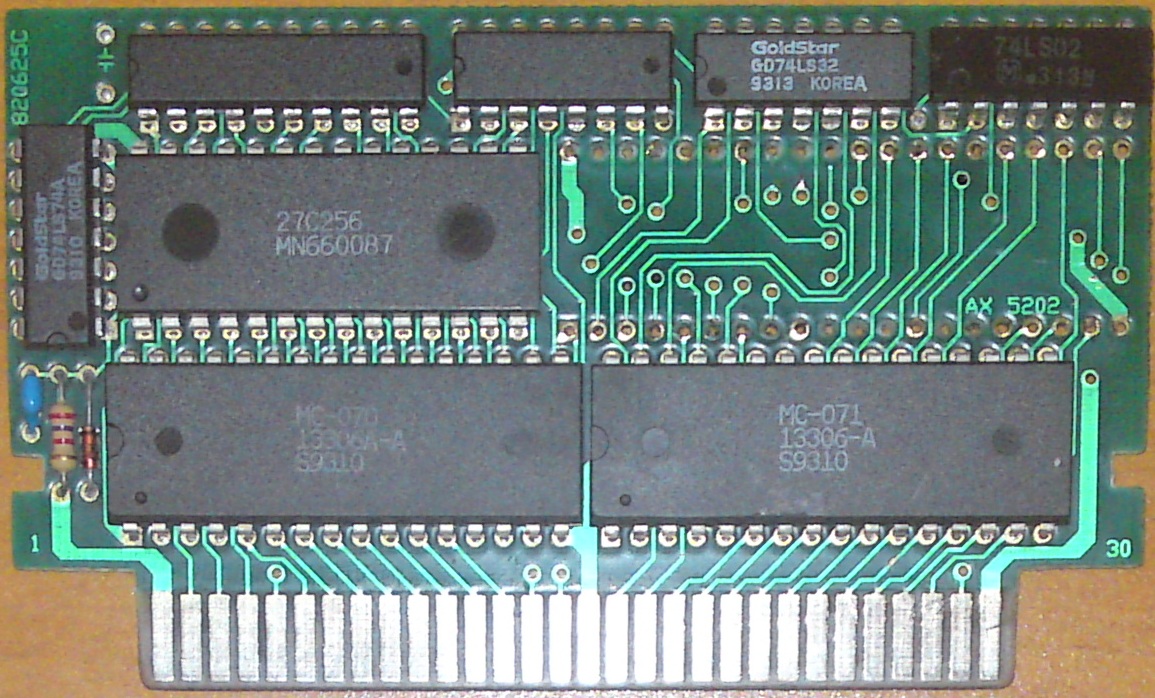
I just want to produce a multigame cartridge by using AX5202P. Can someone help me? Or at least provide me a shot from a multigame PCB which uses AX5202P.
It probably uses the equivalent of an MMC3 or AX5202P for the lower address lines and some sort of register and decoder circuitry for the upper address lines. Kevin Horton has
researched several pirate multicarts and has pictures.
EDIT: Or at least used to have. After the move to kevtris.org, it appears a lot of them have gone 404. But I did find some text descriptions:
http://kevtris.org/files/Mari7in1.txt
http://kevtris.org/files/7in1.txt
http://kevtris.org/files/4in1.txt
http://kevtris.org/files/1min1.txt
Not sure if it can help you, but I was able to dig a page out of Kevin Horton website while trying to dump one of my multicart for the fun of it and it list a few more multicart pcb
http://kevtris.org/mappers/bmc_fam/index.html
Also, I know it's not really useful without actually knowing where to get the cart, but there is one multicart that I feel is what would be needed to make your famous Super Kunio Kun Farsi Multicart (might give you some hope of finding the perfect cart to hack) :
http://kevtris.org/mappers/bmc_fam/BTL_7in1A.html
FARID wrote:
I just want to produce a multigame cartridge by using AX5202P. Can someone help me? Or at least provide me a shot from a multigame PCB which uses AX5202P.
This cartridge picture posted here looks like a MMC3 clone with a 74'161 wired in to control upper address lines. You could modify a normal MMC3 board in the same way if you wanted to do so.
What about other chips? there are 3 TTL chips (74HC161, 74HC153, 74HC138). How should I use them? Unfortunately the picture is not clear enough to find out its schematic.
Hey Farrid, the last suggestion made me remember something that could help you.
http://www.callanbrown.com/index.php?option=com_content&view=article&id=69:nes-custom-multicart-super-mario-all-stars&catid=36:home-console-projects&Itemid=61
Custom MMC3 multicart using reset button to switch game. Only problem you would have IMO is figure out how to fit all your six game on it (not sure of the size of each)
This is really great! That site has a lot of good information. Thanks.
Since I am using Famicom, It seems that I can't use this method :
Quote:
But why was this reset-button method rarely (if ever) used in production NES or Famicom multicarts? The easiest explanation is that the reset signal we're using from the CIC just isn't present on Famicom cartridges, since they didn't incorporate a security chip on the Famicom.
But trying it, doesn't hurt.
Oh sorry I forgot you were using a famicom, that's too bad! Don't waste your time trying it then. Unless we can just simulate that reset signal on the chip using a button installed on the cart... This could maybe be possible.
I can remember once I had a cartridge which worked like this, games changed with pushing reset button!
You can make a reset signal by using M2 (phi2) to charge a capacitor. Then discharge the capacitor through a resistor. I don't know what values to select for the parts, or if there's more to it, I haven't thought it through completely. You'd want it to charge and discharge fairly fast, but not so fast that it'll happen during M2's normal operation (where it's toggling with a 50% duty cycle at 1.789mhz).
Wasn't that also the amusing trick that another multicart used by hooking that reset signal up to the clock input on something like the '161? That way resetting it would clock the counter, which results in selecting a game without using a menu.
Memblers wrote:
Wasn't that also the amusing trick that another multicart used by hooking that reset signal up to the clock input on something like the '161? That way resetting it would clock the counter, which results in selecting a game without using a menu.
That's exactly what the guy in the link posted by SkinnyV in the previous page did.
I haven't looked into exactly how it works yet but this may be of help:
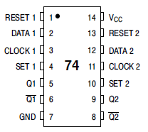
http://nintendoallstars.w.interia.pl/romlab/74ls74.png
Looks to be along the same lines with the cap charging up at first glance.
FARID wrote:
I still have another so called crap! But maybe this is my ace card!!
When I found this cartridge I was just looking for its AX5202P and I was so much hasty that I screwed up the board a little when I was desoldering the AX5202P from the board!
I *highly* suggest you invest in a multimeter, instead. This will make it easier to trace the PCB without destroying it in the process. You don't even have to unsolder any chips. Just put a meter in continuity mode with the beeper, and poke around finding how the chips are connected. This is how I used to do it. It was faster than trying to do it visually. And it doesn't trash the cartridge, which still works after the operation.
A good multimeter is a good investment! I used a crappy one for a while but it's now so much easier with the decent one I bought recently. Like Kevin said, it beat the hell out of desoldering everything. Also, i'm usually able to desolder chip from famicom board with a heat gun pretty fast and resolder them afterward with no damage. It's a bit ghetto but work very fast! Be careful not to do that without good ventilation as breathing the fume could be dangerous though...
Wow, Kevtris is here!

I am not so much smart to dump this cartridge without desoldering the chips, on the other hand it is no use of schematic without owning the code for selection screen which is inside 27C256. Anyway thanks for your advice man!

By the way this cartridge is not my ace card! It really sucks! It does not even support 1MB for PRG and CHR so I can't use its schematic to build my dream 8 in 1 Kunio Nekketsu series translated to Farsi multigame cartridge. I have to find another crap like the one which Kevtris have or get him find his cartridge and give me a shot from its both sides!

Hehe that's also my only way to dump cart lol. I managed to dump part of my Bio Miracle bokutte upa cart before learning Kevin already dumped a long time ago:) It's only giving me issue when pirate cart are using 2 ic for CHR and did not figure out yet how to rearrange and shift the data for those special case...
By the way Farid, do you use a genuine Famicom or a Famiclone? I have recently acquired a pirate multicart with alot of MMC3 game on it but it is not compatible with genuine Nintendo or Famicom console apparently and was developed with clone system in mind. It's actually the best multicart I have ever seen and come with very good game on it, a shame I can't enjoy it on my Nes! The cart is using Flash memory, Chinese pirate have apparently switched to flash as this is the 3rd time I see flash chip in pirate cart.
Memblers wrote:
You can make a reset signal by using M2 (phi2) to charge a capacitor. Then discharge the capacitor through a resistor. I don't know what values to select for the parts, or if there's more to it, I haven't thought it through completely. You'd want it to charge and discharge fairly fast, but not so fast that it'll happen during M2's normal operation (where it's toggling with a 50% duty cycle at 1.789mhz).
Wasn't that also the amusing trick that another multicart used by hooking that reset signal up to the clock input on something like the '161? That way resetting it would clock the counter, which results in selecting a game without using a menu.
Can you suggest me some values for those Capacitor and Resistor? I can test some combinations of them. Please give me a diagram too. Thanks
If you use the circuit I provided the link to eariler the diagram uses a 102 capacitor which is a 1000pF (1nF) cap a diode and 74LS74 chip.
Quote:
I *highly* suggest you invest in a multimeter, instead
I want to listen your advice.
Do you think this multimeter can meet my needs :
MULTIMETER (PDIP ATMega8 version)
If you know any better one, please let me know.
infiniteneslives wrote:
If you use the circuit I provided the link to eariler the diagram uses a 102 capacitor which is a 1000pF (1nF) cap a diode and 74LS74 chip.
This is great, Thanks!
Do you think this can work :

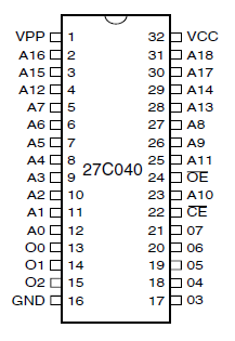
How does it work : By hijacking A19, A18, A17 the AT27C080 function as eight AT27C010 because Signals of A19, A18, A17 can produce 8 different combinations (000, 001, 010, 011, 100, 101, 110, 111) which at a time just one of them can be activated by pushing reset button so it is possible to use eight 256 KB (128PRG+128CHR) games by using this method.

I have not test it yet. I just conclude the idea by combining these two information :
NES Custom Multicart - Super Mario All-Stars
Quote:
If you've read my other tutorials, you might recall my mention of a chip called a 74xx161 (xx being LS or HC, doesn't matter in this case), which was used as a basic mapper in early NES games. The 74xx161 is a 4-bit synchronous binary counter. Basically, upon each strobe of the clock pin, the binary value of the 4 output pins increases by 1. While the output counts up from 0 to 15, then starts over, if you just consider the lowest two pins, you might be able to picture how it can rotate between 4 different digital addresses.
The largest 8-bit EPROMs are 27C080 or 27C8001 EPROMs, which are 8 Mbit in size. which is equal to 1 MByte. Which means each "bank" of ROM space must be 1/4 of this, which is 256KB. 4 banks, 4 combinations of signals (00, 01, 10, 11) coming off the two pins from the binary counter, get it?
In essence, what we're doing is hijacking the two highest address pins of the EPROMs, and letting the NES only choose the lower address pins (A0-A17), so it only sees a 2Mbit ROM space at any one time.
Could you go for 8 banks by using three bits from the 4-bit counter, or 16 games using all four bits? You bet, but then you need your ROMs to be 128KB each for 8 games or 64KB or less for 16 games. The largest ROM included on this multicart will be the 256KB Super Mario Bros. 3 PRG ROM, and to keep the logic simple, this will be the size of each ROM bank.
Is this sort of mod possible for other cartridge-based systems? Probably. This project takes advantage of the fact that +5V is supplied to the cartridge at all times, even when in reset mode, and it also provides a direct link to the reset signal. I'm not sure this applies to all systems. Other systems might cut power to the cartridge, or might simply not provide any means of detecting a reset.
And :
74LS74 used in many 2in1 Reset based carts

I want to know what is the difference between 74xx161 and 74xx74? Which one is better for my purpose? Even if there is a better choose other than these two, specially something smaller, please let me know.
What is the full part number of D(148)?
http://www.dealextreme.com/p/dt-830b-ha ... 6f22-53130
Quote:
I want to know what is the difference between 74xx161 and 74xx74? Which one is better for my purpose? Even if there is a better choose other than these two, specially something smaller, please let me know.
'161 - 1x 4-bit counter
'74 - 2x 1-bit flip-flops
If you only need 2/4 states (games) use the '74, you can turn it into a 2-bit ripple counter. If you need 5-16 states use a '161.
Holy flying pigs Batman! Is that an NES cart on a breadboard!?!?
Wow...
Much respect man. Much respect.
Anyway, isn't your diode backwards in that schematic?
There was a post on these boards about multicarts used on the Atari that used the reset button as the counter clock, but I can't for the life of me find it. If we could I know there is an NES mapper that works the same way. We could look up the PCB on Bootgod's database and have a look-see.
Comparing with this :
It is in the right direction, I think.
Quote:
If we could I know there is an NES mapper that works the same way. We could look up the PCB on Bootgod's database and have a look-see.
Reset based multigame cartridges doesn't need any kind of especial mapper at all. The only restriction is, all the games inside the cartridge must have the same mappers, that's all. It is possible to make a 16 in 1 (with 161 TTL and 27C080) cartridge, even theoretically it is possible to build a 64 in 1 (? maybe with some other kinds of TTL which have more output lines).
My problem is still stands :
Quote:
games show up randomly! I feel that it is because of voltage which becomes unstable by pushing reset button. How can I fix it?
Let me say that differently: There is at least one NES or FamiCom cartridge that uses a reset-based game selector that uses this same method. If we knew which one we could see how it was made.
Also, if you used an 8-bit binary counter you could make a 256-in-1 multicart, but I'd hate to be a fan of game 256
Unfortunately I can't see that image right now. I'll have to look again later. But the way I was thinking the diode is preventing any positive current from reaching the clock pin on the '161. Does pressing the reset button change the selected game it the order you expect?
As for the rest of it, your parallel input pins have been left floating. Perhaps that's why you are getting a random start state? Try to tie pins 3 through 6 to ground and see if that fixes your issue. I'm no expert, but I've always been told to not rely on floating inputs to pull high.
Quote:
if you used an 8-bit binary counter you could make a 256-in-1 multicart
How are you calculating it? At normal state we have 27C080 as the largest EPROM which is 1024KB, on the other hand the smallest games are NROM which have 16KB for PRG. By division 1024 to 16 we have 64 games in 1 cartridge at most.
Quote:
Does pressing the reset button change the selected game it the order you expect
It is working fine. I just have to push-hold-release the reset button, in that way games show up in right order.
Quote:
As for the rest of it, your parallel input pins have been left floating. Perhaps that's why you are getting a random start state? Try to tie pins 3 through 6 to ground and see if that fixes your issue. I'm no expert, but I've always been told to not rely on floating inputs to pull high.
Regarding the function table of 161, count mode is activated when the MR, CEP, CET, PE are high and Clock goes from low to high, but as you can see for D or P inputs the required voltage is X which means don't care, now the question is what does it mean really?!
You are only limited by what you can make, you ca stick as large of a ROM on it as you want if you can wire it up, but I don't think there's even more than 64 NROM games, so might be useless to do 256. Good luck!
3gengames wrote:
I don't think there's even more than 64 NROM games
I searched BootGod's NesCartDB for commercial games with mapper 0, one result per game for all regions: Results 1 through 25 of 118. There are 208 other games with 256 Kbit or smaller PRG, many of which can probably be hacked down to one CHR bank with only minor graphic reductions (such as the version of Tetяis that's labeled "TETRIS 2" on pirate multis, and the eight mapper 185 games).
But I agree that if there are more than 8 games, a menu is definitely warranted. Changing channels with reset is like looking for something on TV with just the channel down button: OK for the farmer five but impractical for cable.
This cartridge is compatible with AT27C080 and AM29F040. I haven't tested it on cartridge yet but it should work. Any kinds of idea for improvement would be appreciated.


Is there any way (other than using UV EPROM Eraser) for erasing AT27C080? How about I put it in front of sunlight? It is one of UV source, doesn't it?!
As I understand it, erasing UV EPROM needs a stronger UV source than sunlight alone.
Sunlight can cause UV EPROM erasure but it's unreliable for erasing an EPROM for reprogramming, but it could cause a programmed EPROM to have bits reset ruining whatever program is on the EPROM which is why you should cover EPROM windows with stickers unless it will be contained in a cartridge or something else at all times.
Sunlight isn't the right frequency iirc. So what happens is that maybe 1 or 2 bits get flipped over x amount of time. But if you want to really erase a rom you're gonna need something more suited for the job.
You can get really cheap eprom eraser on ebay. You can order from china with free shipping for less than 15$. Would beat the hell out of leavimg your eprom in the sun:D Also, I always wondered if building a UV LED arrays would work for erasing eprom... I have a load of UV LED at home but was always too lazy to wire them up and try since I was able to get a uv eraser for almost nothing.
By the way, I was wondering what software you were using to design pcb. Also, are you etching them at home? Because if you do I was curious how you manage to etch double-sided board without running into too much lining issue.
Quote:
By the way, I was wondering what software you were using to design pcb.
I am using Proteus 7.7
Quote:
Also, are you etching them at home?
Yes, at home!
Quote:
how you manage to etch double-sided board without running into too much lining issue.
I am using a method called Print-Iron :
How to make PCBs at home
For making a double sided PCB :
Cut the board at the size of front layout picture
Iron the front layout
Wait until the board become cool
Place the bottom layout on the board and adjust it by using the edges marks (dots and connectors)
Iron the bottom layout
Use FeCl3 for erasing the unnecessary Cu (copper) from the PCB
SkinnyV wrote:
By the way, I was wondering what software you were using to design pcb. Also, are you etching them at home? Because if you do I was curious how you manage to etch double-sided board without running into too much lining issue.
I recommend design spark, it free and has nice tutorial to get you going. What do you mean by lining issue? Do you mean lining up the two sides?
From what I've seen the best way to do double sided boards is tape you print outs together on the one side. You can hold the paper up to the light to make sure you've got them lined up properly. Then sandwich your board between the two and start ironing.
Yes, I did mean having the 2 side lining up properly
English is not my native language and sometime I write or say something using a syntax that would be ok in my language but isn't in English. I always thought that etching double-sided pcb at home would be quite complicated but I guess I should try it out.
I wanted to try to learn Proteus as it sound like it's becoming quite a popular design software these days but thought it was kinda too powerful for my need. Would you agree to share the library for the famicom connector Farid?
SkinnyV wrote:
Yes, I did mean having the 2 side lining up properly
English is not my native language and sometime I write or say something using a syntax that would be ok in my language but isn't in English. I always thought that etching double-sided pcb at home would be quite complicated but I guess I should try it out.
Yeah that site Farid gave is really good, it's also where I found the link (at the bottom) to another site that gives the tips on double sided boards:
http://myweb.cableone.net/wheedal/pcb.htm
Quote:
Would you agree to share the library for the famicom connector Farid?
For sure.

Here you are :
Download Proteus PCB and SchematicTry to change the schematic for NES.

Quote:
English is not my native language
What is your language?
SkinnyV has listed "Location: Montréal". Montréal is the big city in Québec, a province of Canada where they speak a dialect of French. And I've been told that
Québécois French sounds like it has a thick "Southern drawl" from a Parisian point of view.
EDIT: fixed Montréal's status
"A dialect of French". Find it kinda funny.
Well, it's not
that different, it's just the accent and some idiotisms that are different. For us, French from Paris sound snobbish.
Bonjour SkinnyV!
I agree french from Paris sounds EXTREMELY snobish, but the Canadian dialect is even worse. The accent is funny but you don't get half of their words.
The truth is that only people from my region speak french PROPERLY
Not everyone speak bad french in Quebec, I speak very good french myself because my mom taught me properly. Also, Montréal isn't the capital of Québec, the city of Québec is actually the capital of the province of Québec:) Also, I agree that it is not really a dialect, just a slight modified version of France's french with different accent, butchered word and different slang:)
By the way Bregalad, what region are you referring to that is supposedly the only place where they speak proper french?

And thanks Farid for the library! I'll play with it tonight to try and learn Proteus. Also, sorry about your thread going a bit off-topic with my native language, let us know how your PCB turn out!
SkinnyV wrote:
You can get really cheap eprom eraser on ebay. You can order from china with free shipping for less than 15$. Would beat the hell out of leavimg your eprom in the sun:D Also, I always wondered if building a UV LED arrays would work for erasing eprom... I have a load of UV LED at home but was always too lazy to wire them up and try since I was able to get a uv eraser for almost nothing.
UV LEDs will not erase an EPROM. You need relatively short wavelength UV, around 250nm, before an EPROM will erase. A "Germicidal" bulb is what you need. Though as others have said, cheap erasers are available on ebay and stuff that will work. The sun does not work very well, and is not reliable enough to erase an EPROM. If an EPROM is not erased fully, it may check blank but will error out during programming.
Is there any way to change the function like this :

What TTL should I use for this 3-Mode loop?
FARID wrote:
Is there any way to change the function like this :
What TTL should I use for this 3-Mode loop?
First you need to setup your counter to reset when it counts to three (11 in binary). For that you use an AND port from a 74LS08 with the output connected to the clear pin of the counter... I like 74LS393 more than 74LS161 for the counting purpose, but it's because I have a LOT of 74LS393 chips here...
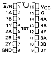
Now for making the 256KB bank work you need to detect that the counter is at "10" and add a new chip (I recommend 74LS157 as it selects two to one) that reconnects MC and MP17 lines to the mapper chip. You can simply connect the input selector pin from the 74LS157 to the high bit of the counter.
A input from the 74LS157 goes to GND, B input of 74LS157 goes to mapper chip pins for PRG and CHR.
Hope that ideas the I posted here help with your goal.
And this was my first post. Hope we get along as I plan to post a lot here !
Please someone correct my mistakes :

Quote:
First you need to setup your counter to reset when it counts to three (11 in binary). For that you use an AND port from a 74LS08 with the output connected to the clear pin of the counter...
I am not so much expert but I think I should use a NAND gate because for enabling reset mode I need a Low voltage. For producing a low I should connect 1 and 1 to a NAND gate.
Is there any way to control Reset without using any extra gates?
If you're really into not adding more chips you might want to look this link (lol):
For an DTL implementation:
http://www.6502.org/users/dieter/mt15a/mt15a_3.htm
(read the whole article if you can as it's a great read ! but the page I linked to has an discrete parts circuit you can use...)
Or you can use the "Mickey Mouse logic" (I think Kevtris used that term on one of his pirate mapper articles I read many many years ago):
http://en.wikipedia.org/wiki/Diode_logic
The diode logic trick actually helped me to save some board space on a project I built for MSX computer with an YMF278B chip (Moonsound) several years ago...
Also for the 74LS157 you only need to use two ports of it:
A-------|157\___Y_ Y will be GND if Sel pin is 0 and will be A17 if SEL is 1
B-------|___/
Sel------/
connect GND to A
Connect A17 from AX chip to B
Connect Sel to high bit from counter.
Strobe goes to GND.
Repeat for CHR bank (use other port, chip has four)
I think this is better :

But there is still a problem. For enabling Reset of 161 a low voltage is needed but Y3 is producing 0 , 0 , 0 and then 1 so it will not work at all in this way and it will be in a loop on first step but if I just replace 161 with something else like 74LS393 which its Reset needs High to activated I think there will be no problem, right? But It seems 74LS393 is more complicated than 161 and there are two pairs of Q and even Clock in it! What the hell are they? Is there any better and simpler TTL than 74LS393, something like 74HC74?!
I think it is better to use two separate ports for MC17 and MP17, it is more safe, don't you think?
My conclusion for A1 and A4 (of 157) : it is possible to use either GND or A17 (coming from 161), but I prefer to use A17 itself because I think using A17 in PCB designing is more convenient than GND lines.
Actually 74LS393 is simpler because it just counts pulses you put on the clock pin.
It's a binary counter and each time you clock it, it adds +1.
74LS161 is a sort of register file with carry in and out ...
So 161 is more complex than the 393. In fact 393 is made of several 74s in "daisy chain"...
And it has TWO 4 bit counters so you only use half of the chip for this...
Now, you can temporarily remove the 161 from the circuit and test if setting:
H L
I O
---
00 = first game (256KB)
01 = second game (256KB)
10 = third game (512KB)
Woks as expected...
It seems I can't replace 161 with 393 at all. There is a problem with Clock. Enabling 161 count mode require a Low to High signal but for 393 it must be a High to Low signal. So I need an IC which has a Low to High Clock and Active High Reset. Is there any chip like this?
I am really confused about M2 signal, M2 is always on high state, by pushing reset button it goes to low, by releasing, it goes to high and stays at that state. My conclusion is : It should work with both Low to High and High to Low Clock signal, but in practice it is not working, why?
Still I can't analyze the function of 102 Capacitor and 148 Diode. Can someone analyze their function?

Phase2 (PHY2) signal is pulsing at approximately 1.7mhz It's not high all the time.
The PHY2 signal keeps the capacitor charged through the diode (it's pulsing) and when you hold reset the pulses stop. That makes the capacitor discharge through the 161 clock pin, making it detect one pulse (due to state change).
74LS393 works for me with the same diode+capacitor circuit... I don't see how it would not work for you.
M2 is about 3V and after crossing 148 Diode it becomes about 1V. By pushing and holding the reset button M2 becomes 1.25V and after crossing 148 Diode it becomes 1.5V.
I couldn't even get 74LS74 work, It does not show any reaction to my reset signal. For 161 it is very unstable and seems to be a little random.
It's "PHI2" (symbol used on mathematics which be the Greek letter phi) not M2 and like I said it's pulsating so measure voltage isn't very efficient...
Also I believe the diode has to be of Schottky type.
Means that the voltage on the output will be higher than what you would be getting from an rectifier diode...
I used 1N4148 diode for mine. Anyway, I measured my circuit voltages to try to help you out. It's at 0.8v when the system is running and 3.57v when reset is held down.
And you might want to check if your diode is really an 1N4148...
PHI2 is held high during reset.
qbradq wrote:
PHI2 is held high during reset.
Exactly.
I was told that when I was doing my multicart and I followed the idea. I saw the circuit with the 1n4148 and capacitor being used to reset the game latch on a multicart. I just copied the circuit on my cart and it worked. I used the 74LS393 as I said.
One thing to take notice, the 74LS393 reset is inversed. So to make the counter run you need to set it to 0 and 1 resets it. That's why you use an AND port yo reset it. Why you don't try an NAND port for 74LS161 ?
During reset signals are high impedance (Hi-Z), not logically high.
kyuusaku wrote:
During reset signals are high impedance (Hi-Z), not logically high.
But then there should be an (possibly internal) pull up or something because it goes logic level 1 when reset is held.
The Hi-Z state applies to a stock 6502, right ?
Nope, no pull up, any voltage is either bus capacitance or supplied by a following input stage as in the ROMLab circuit:
http://nintendoallstars.w.interia.pl/romlab/74ls74.png
(I'm Calpis on Assembler that mentioned it)
I don't think it applies to MOS and second source 6502, the clock generator directly drives the pin (and no pins tri-state but the data bus). The 6510 however has an external bus control feature so perhaps it does.
Just keep in mind that the 2A03 is not a 6502 by any stretch. Would the
Visual 2A03 help clear things up? I've tried fiddling with it, but I can't seem to get the reset signal asserted, even using the URL interface.
Well the 2A03 contains a vanilla 6502 (with decimal mode cut out), but I/O to/from the 6502 has additional buffering. The layout clears everything up (sort of, it's extremely tedious transcribing it into transistors visually).
I think the fact that 6502 quirks and the undocumented/illegal/whatever opcodes work on 2A03 is already a clear indication that it's a close enough clone of the 6502, to the schematic level. Otherwise there was no reason to replicate the CPU so fully, especially the illegal opcodes, as Nintendo themselves wouldn't recommend developers to use them, why should they care to make them work in the first place?
The illegal opcodes as they are called are the same not because they were put there but because it's the same incomplete behavior. There are reasons to why the undocumented/illegal opcodes behave the way they do.
Yeah, these extra opcodes were just side-effects of how the opcodes were implemented, so if you're going to make a clone of the chip but aren't applying the same schematic there isn't much reason to "put back" these extra opcodes.
The "unofficial op-codes" are a side-effect of the basic architecture of the 6502, especially the decode unit. I won't go into details as I'm no expert, but I'd caution you to make a distinction between assumption and deduction.
Gilbert wrote:
if you're going to make a clone of the chip but aren't applying the same schematic there isn't much reason to "put back" these extra opcodes.
Other than that some of the unofficial opcodes can be rawther
useful, and one of the SKBs is needed for Puzznic.
Works fine with LED :

It should work on 29F040 with three games (256 + 256 + 512). No need for any extra gate for resetting task
Now, that's clever usage of the counter circuit.
TLROM Mapper4 Multifunction MultiGame Cartridge :
Download Proteus v7.7 PCB layout file
Front :

Back :

Use 404 to enable :

Use 80 and 808 to enable :

use 80 and two 804 to enable :

I found out something about 393. There is a difference between 74HC393 and 74LS393 :
what is the difference between 74ls and 74hc
To use HC family, circuit needs an extra resistor (2.2Kohm or more)


I was using HC family without any resistor and I had a random result on game selection.
Because I was relying on this information :
Quote:
If you've read my other tutorials, you might recall my mention of a chip called a 74xx161 (xx being LS or HC, doesn't matter in this case),
That's why I had problem with this circuit at first.
Makes a little sense, since how HC parts are FETs and have super high imput impedance. The LS are TTL so the pull up is effectively built in with the lower input impedance they have.
infiniteneslives wrote:
Makes a little sense, since how HC parts are FETs and have super high imput impedance. The LS are TTL so the pull up is effectively built in with the lower input impedance they have.
It has more to do with the use the HC parts are meant for. They're meant to be compatible with both LS and 40xx CMOS devices so they have minor changes on their design to achieve that.
I save myself the hassle by sticking to use only 74LSxx parts which I am used to.
UNROM Mapper 2 MultiGame Multifunction Cartridge :
Download Proteus v7.7 SP2 PCB layout file
Front :

Back :


Aww, all the images are ruined. Does anyone have them archived?
What do you want exactly?
I'm not sure, but I couldn't see the images in the posts. "Want free stuff? Go to XWinner.com"


