For the past few days I've been hard at work trying to get kevtris' circuit up and running, and so far have the following:
http://kevtris.org/IMG_2306.JPG
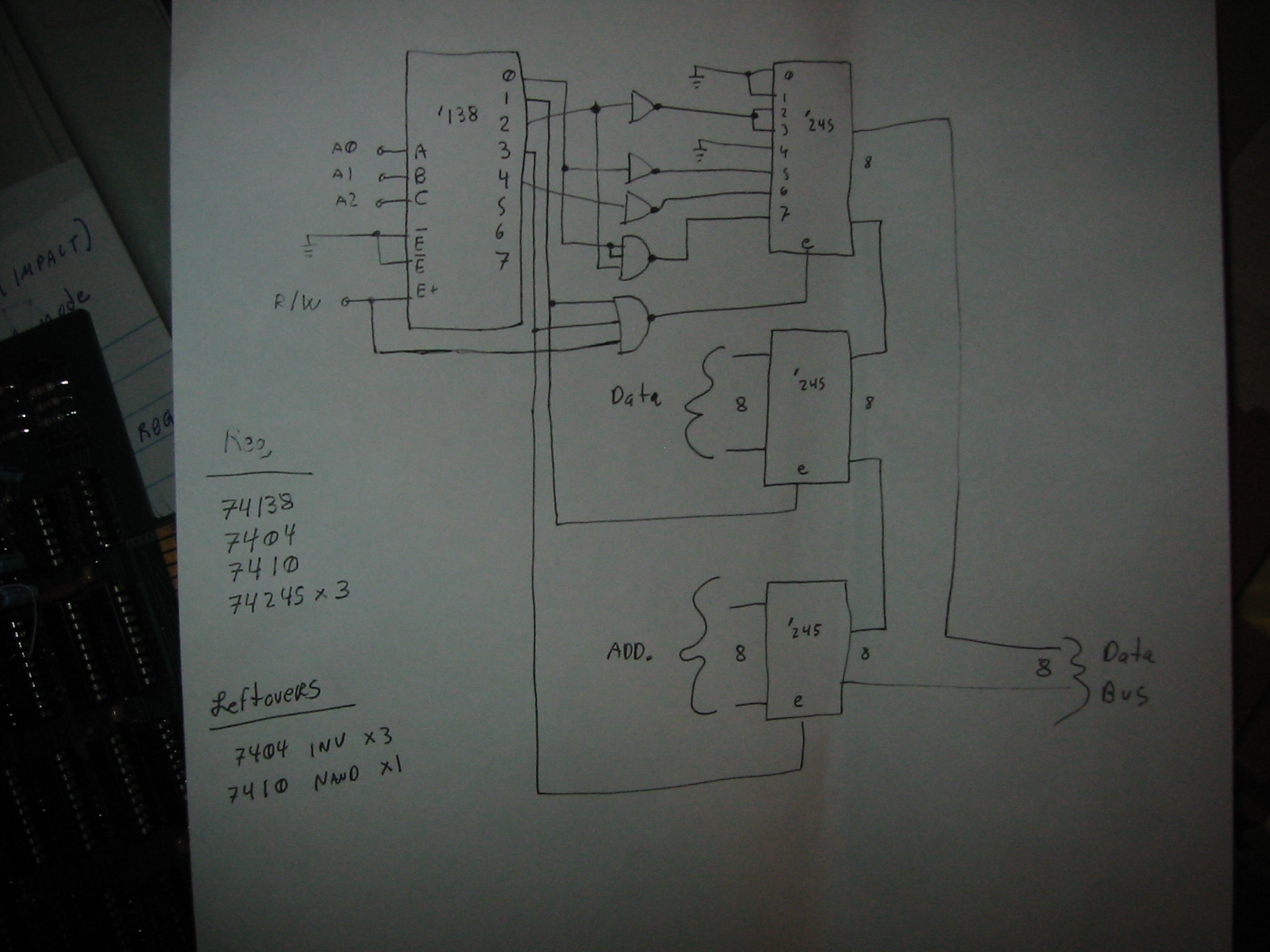
This circuit, fully implemented. I have my AVR grabbing rising edges from the 3rd output of the 138, which lets it know when is the best time to update the data and address ports. Discussion about this can be seen here.
http://personal.stevens.edu/~jlupinsk/irc.txt
I wrote up some basic code to try to turn the noise channel on, but so far no luck:
http://personal.stevens.edu/~jlupinsk/code.txt
I have pin 2 of the 2A03 connected to a 386 op amp with a 20x gain, any higher than that and I pick up more buzz than actual sound. My 2A03 is connected as such:
Pin 2 -> 386 -> speaker
/RST toggled by my AVR
A0-A2 -> 74HCT138
GND is grounded
D0-D7 -> bank of 3 x 74HCT245's
CLK, using the original NES crystal with one of the unused 74HCT04 gates, as such: http://go.mibbit.com/thumb.php?x=32&y=32&url=http%3A%2F%2Fwww.mpdigest.com%2Fissue%2FArticles%2F2008%2FMar%2FCrystek%2Ffig1.jpg (This is probably an issue, but I couldn't find any circuit other than this which reliably uses a >10Mhz crystal)
Pin 30 is grounded
/NMI and /IRQ are pulled high
R/W going into the '138 and the gate
+5VCC coming from a clean switch mode PSU, with additional filtering caps
Most likely causes that it won't work:
Crystal circuit
Initialization of the CPU doesn't work
If statements are too slow, interrupts occur quicker than state function can iterate
Something about the actual audio out fromt he 2A03
Could anyone look over the code and offer some advice? I've commented most of it to make it easy to follow.
http://kevtris.org/IMG_2306.JPG
This circuit, fully implemented. I have my AVR grabbing rising edges from the 3rd output of the 138, which lets it know when is the best time to update the data and address ports. Discussion about this can be seen here.
http://personal.stevens.edu/~jlupinsk/irc.txt
I wrote up some basic code to try to turn the noise channel on, but so far no luck:
http://personal.stevens.edu/~jlupinsk/code.txt
I have pin 2 of the 2A03 connected to a 386 op amp with a 20x gain, any higher than that and I pick up more buzz than actual sound. My 2A03 is connected as such:
Pin 2 -> 386 -> speaker
/RST toggled by my AVR
A0-A2 -> 74HCT138
GND is grounded
D0-D7 -> bank of 3 x 74HCT245's
CLK, using the original NES crystal with one of the unused 74HCT04 gates, as such: http://go.mibbit.com/thumb.php?x=32&y=32&url=http%3A%2F%2Fwww.mpdigest.com%2Fissue%2FArticles%2F2008%2FMar%2FCrystek%2Ffig1.jpg (This is probably an issue, but I couldn't find any circuit other than this which reliably uses a >10Mhz crystal)
Pin 30 is grounded
/NMI and /IRQ are pulled high
R/W going into the '138 and the gate
+5VCC coming from a clean switch mode PSU, with additional filtering caps
Most likely causes that it won't work:
Crystal circuit
Initialization of the CPU doesn't work
If statements are too slow, interrupts occur quicker than state function can iterate
Something about the actual audio out fromt he 2A03
Could anyone look over the code and offer some advice? I've commented most of it to make it easy to follow.