I bought an AV Famicom a couple of months ago, and I have played completely through about 3 games on it (2 FC 1 FDS). So I know it was working perfectly before today.
Today I fired it up with the FDS connected to it and realized that I had forgotten to plug the controller in. I plugged the controller in and the game froze. At the time I assumed that this was because I had nudged the FDS RAM adapter while holding the back of the unit.
I reset it and everything looked fine, but when I hit start to begin the game nothing happened. I tried another game, and similarly, nothing happened. I then swapped controllers and still nothing.
It seems like the controller port stopped working. Am I just screwed, or is there some way to fix this? I know newer systems all seem to have fuses, in the controller ports, but I'm guessing this one doesn't (haven't opened it up yet). Do I need to test/repair some mosfet or something?
Any help would be great.
Thanks.
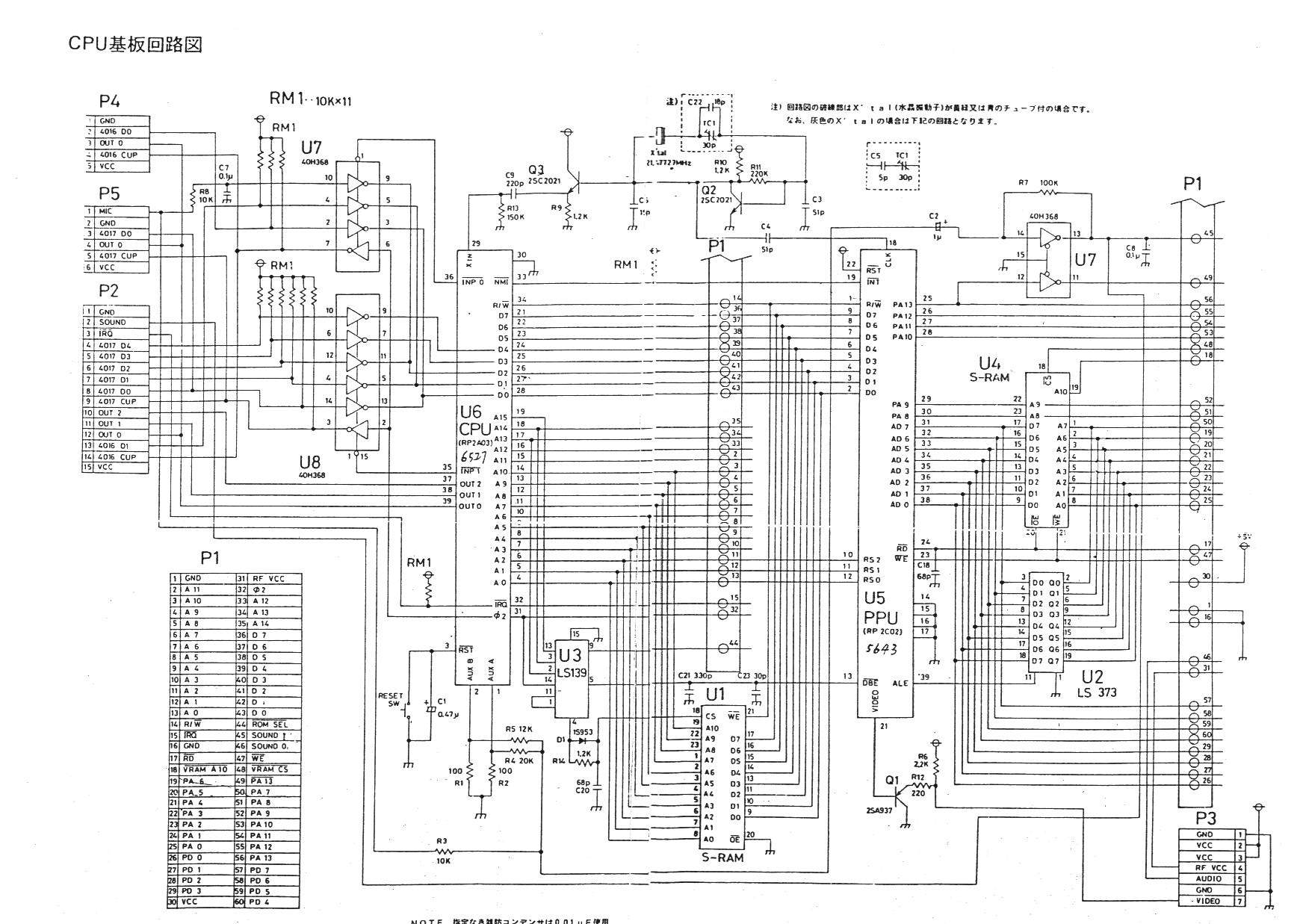
Here's the Famicom schematic, it's probably the same for the AV Famicom.
http://nesdev.com/Ntd_8bit.jpg
Could try replacing the 40H368 with an equivalent part. Perhaps CD74HC368?
Is there a way to test it first to see if it is the problem?
Do you have any EE tools? (oscilloscope, &c) ? If so, that's definitely the least error prone solution.
If not, you could probably make a tool out of an LED and a resistor going from D0 on the data bus on the '2A03 to the pre-inverted output of the '368.
(Warning: These names are correct for the schematic Memblers posted. They might have changed. However, they're the same on my US NES.)
That would be: Connect pin 3 of U7 to a 5-10kohm resistor, connect that to the long lead of an LED, connect the short lead of the LED to pin 2 of U7). If it lights, that would strongly imply that the controller were successfully sending a "button pressed" condition.
Because of how the Famicom/NES reads its keypad, it should flicker unless you're pressing all the buttons simultaneously, and will only flicker while the console is running a game.
Note that if the LED is pointed the other direction it will be lit all the time.
Don't use a resistor smaller than 2k, it could (at best) make things function incorrectly, at worst it could damage parts. Note that the glow may not be very bright. Clear LEDs will be easier to see.
Please forgive me if this is a stupid question, but I'm trying to understand what this means.
If I make the tool out of an LED and resistor, and touch it to those two points (assuming that I have the polarity right) it will simulate a button press, or do I need to actually press a button on a connected controller to see it light up.
Either way, if it does light and the system is still acknowledging controller signals, does that indicate that 40H368 is faulty? If it doesn't light what does that imply?
Thanks for bearing with me.
I think it would lights as each of the 8 bits are read out of the controller, but how could you even see it blink if the bits are read at intervals of under 1 millisecond?
I hate to wuss out on something like this, but is there anywhere I could send this thing to get it repaired? I'm guessing not, but I hope I'm wrong about that.
It just seems like I'd be more likely to ruin it beyond repair than fix it - I've never desoldered an entire IC before. You guys are obviously light-years beyond me in understanding this stuff.
I haven't given up or anything, I just want to know a little more before I proceed.
For instance, is the IC that I've been pointed to - the 40H368, responsible for processing controller signals? It seems like you're just guessing that the AV Famicom and Famicom share the same design. Would it be helpful if I posted hi-res photos of the PCB?
I looked up the suggested replacement part and that seems like a relatively cheap repair if it's the problem; assuming I'm looking at the right thing:
http://www.mouser.com/Search/Refine.asp ... =CD74HC368
Even though they all have the same part number, they all appear to be slightly different. Do I just compare what I see here with the picture, or is there some more specific way to make sure I get the right thing?
You guys have been awesome so far, thanks for all the help.
It will light if a button is pressed.
If it lights, it implies the problem is neither with the controller nor the '368.
From personal experience, I've been able to see LEDs that were lit for 25us and off for a second, so it should work out.
I just tested this on my NES with the Legend of Zelda. The LED was barely lit all the time, a little brighter when I pressed any button except A, and much brighter when I hit A. For other games, it might be much brighter when you hit Right (A and Right are first and last, respectively, from the controller)
(If you don't get 3 different brightnesses, one of which could be off, something's broken)
So, if it doesn't light, and I have independently verified that the controllers work on a different system, that means that there is definitely a problem with the '386?
I'll probably hit Radio Shack on Tuesday to get the the LED and resistor.
I've been looking at this PCB for a while here, and I'm willing to admit that I may be retarded but I don't see U7 on it. I see everything up to U6. Nor do I see anything with a 368 printed on it.
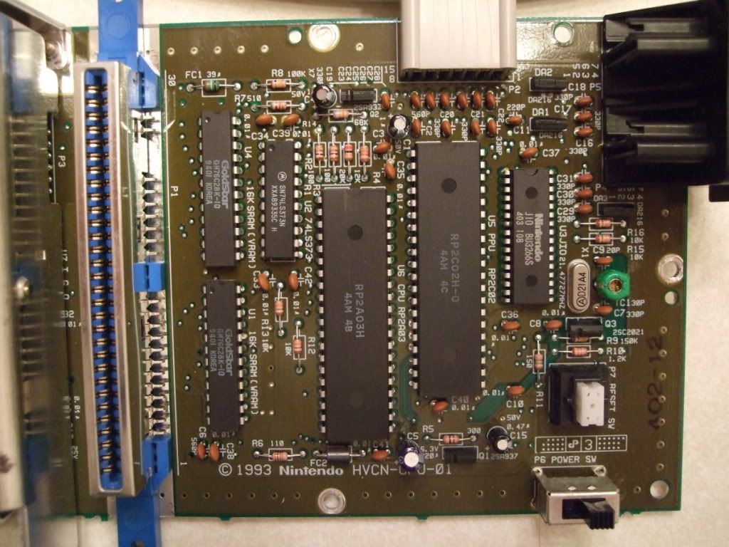
Any ideas where to go from here? Am I looking at the PCB wrong, or does this require a different approach?
Just FYI, there are no IC's behind the shielding to the left of the pic, just a couple of caps, a transformer, a resistor and the AV and power sockets.
Since when does radio shack actually sell components, and not just cell phone plans?
Uh-oh.. it looks like Nintendo replaced those parts with a custom IC (U3 JIO). I imagine that part is probably in a top-loader NES also. It may be hard to find it elsewhere..
Another option could be a separate board with couple '368s and some pull-up resistors, wired in to where that chip goes.
I was afraid of that.
I would love to build a separate board, but I wouldn't know where to begin. Can you tell by looking at it what I would have to do? I know that I'm asking for a lot here, and I'm really thankful for any help.
In theory, is there a way to test the U3 the same way I was going to test the 368, or would you need to see a revised diagram to tell for sure?
Yes, you could test it the same way by finding the same pins (one is controller #1's D0 and the other is the CPU's D0). The pinouts of those are known, if you check the available docs.
Unfortunately I couldn't find a pinout or any info for the BU3266. So what you'll have to do is get a continuity tester (or a multimeter with that function), and by cross-referencing the Famicom pinout (P4 and P5 on there, but if you want to use the lightguns and stuff you may need D3 and D4) with an NES controller connector pinout, create a pinout doc for the BU3266.
So in addition to the 2 '368 ICs, you'll need maybe 8 10kOhm resistors. You'd connect one end to the +5V VCC line, and the other end as shown in the schematic.
At Radioshack you should be able to find a "general purpose board", or a grid board that can be soldered to. You could pick up the multimeter there too (Harbor Freight should have those cheaper too if you have one of those nearby). Mouser may have all that stuff too, I haven't checked. Just make sure the board you get will be big enough to hold it all.
I don't have much experience with wiring diagrams so I'm not sure that I'm reading it right. Is this saying that D0 is pin 28? And if that's correct, it would be the eighth pin from the bottom on the right side according to the orientation in the photo I posted? And to test which point do I connect the resistor to and which to the long leg of the diode?
Let me see if I understand the next part - you're saying to trace the leads from the controller/accessory ports - P4, P5, D3 and D4 to the BU3266, then compare the map of what the BU3266 is connected to with the U7 and U8 on the diagram to see where the new 368's should be connected. Assuming that's right, I don't understand what the resistors are for.
Thanks
samson7point2 wrote:
I don't have much experience with wiring diagrams so I'm not sure that I'm reading it right. Is this saying that D0 is pin 28? And if that's correct, it would be the eighth pin from the bottom on the right side according to the orientation in the photo I posted? And to test which point do I connect the resistor to and which to the long leg of the diode?
Correct. To find out where on the JIO chip to connect the diode, locate D0 on the controller port and trace it to the appropriate pin on the JIO chip (or really could connect it anywhere on that same PCB trace between the 2).
Quote:
Let me see if I understand the next part - you're saying to trace the leads from the controller/accessory ports - P4, P5, D3 and D4 to the BU3266, then compare the map of what the BU3266 is connected to with the U7 and U8 on the diagram to see where the new 368's should be connected. Assuming that's right, I don't understand what the resistors are for.
Yep, that sums it up.
The resistors, in this configuration are called "pull-up resistors". This is so if you don't have any controllers connected (or no signal on any particular input line, controllers don't use them all) the '368 chips will have a valid signal on their inputs. It will be "pulled" high by the resistor. Without it, the 368's inputs would be "floating", which can cause very very bad things to happen (probably would fry the chip and drain a ton of power because the input could rapidly switch on/off). So don't forget, never leave any input pins floating (unconnected).
I may have been wrong about the amount of resistors needed. If an input isn't used however, you can connect it straight to +5V VCC.
I think I get the pull-up resistor thing, I'm just not sure where exactly they go. But I'm going to put on my thinkin' brain and try to reason it out.
If I get two 368's and connect them to the controller traces on one side and the data bus (I'm guessing on the data bus thing) on the other side, I'll have some unused pins.
All of the unused pins get connected to +5V VCC (I have no idea what that is, by the way, but I'm guessing it's the opposite of ground and it'll be clearly marked on the PCB somewhere?) and all of the ones that do connect to controller pins need a resistor between the IC and the trace? Or is the resistor attached to ground AND the IC?
samson7point2 wrote:
I think I get the pull-up resistor thing, I'm just not sure where exactly they go. But I'm going to put on my thinkin' brain and try to reason it out.
If I get two 368's and connect them to the controller traces on one side and the data bus (I'm guessing on the data bus thing) on the other side, I'll have some unused pins.
All of the unused pins get connected to +5V VCC (I have no idea what that is, by the way, but I'm guessing it's the opposite of ground and it'll be clearly marked on the PCB somewhere?) and all of the ones that do connect to controller pins need a resistor between the IC and the trace? Or is the resistor attached to ground AND the IC?
Yes, VCC is the opposite of GND. It's the main power line pretty much. GND is also called VSS, so watch out for that similar name.
The resistors are connected to both the IC and VCC (not ground). However for the unused pins, before hooking them up be sure they are inputs. Connecting an output to VCC or GND would be bad, I'm not sure what that'd do exactly. The sure way to check which pins are what, is with a chip datasheet. There's actually one here on the site:
http://nesdev.com/74HC_HCT368_CNV_2.pdf
You'll know a lot more about electronics by the time you're finished with this repair job.
