This is an edited version of the MMC1 portion of the CPLD code in the UNES. Hypothetically it is connected to 256k PRG ROM and 128k CHR ROM, with no RAM. Unfortunately all I can achieve is a black screen on powerup. Can anyone see anything here that is incorrect?
Code:
--**************************************************************************************************
-- SHIFT REGISTER PROCESS
--**************************************************************************************************
PROCESS (prgcein)
VARIABLE count: INTEGER RANGE 0 TO 5; --THIS IS THE PLACEHOLDER SHIFT THING
BEGIN
IF(prgcein = '0' AND prgcein'EVENT) THEN --CLOCK IN WHEN PRG /CE GOES LOW
IF(prgrw = '0') THEN --PUT PRG R/W MUST BE LOW AS WELL
IF(prg_data(7) = '1') THEN --IF THE RESET BIT IS SET
count := 0; --THEN RESET THE COUNTER
R0 <= R0 OR "01100"; --init reg0 at 0x0c
R1 <= "00000"; --reset the rest to 0x00
R2 <= "00000";
R3 <= "00000";
ELSE --OTHERWISE THIS IS A NORMAL CLOCK IN OF DATA
q_s(count) <= s_in; --PLACE THE DATA INTO THE NEXT MSB
count := count + 1; --INCREMENT THE COUNTER
IF(count = 5) THEN --IF WE'VE CLOCKED IN 5 BITS
count := 0; --RESET THE COUNTER
CASE prg_addr_in(14 DOWNTO 13) IS --OUTPUT THE REGISTER BASED ON THE ADDRESS
WHEN "00" =>
R0 <= q_s;
WHEN "01" =>
R1 <= q_s;
WHEN "10" =>
R2 <= q_s;
WHEN "11" =>
R3 <= q_s;
END CASE;
END IF;
END IF;
END IF;
END IF;
END PROCESS;
--**************************************************************************************************
-- MIRRORING PROCESS
--**************************************************************************************************
PROCESS (chr_addr_in, R0)
--IF R0(1) = 1, THEN R0(0) DEFINES HORIZONTAL OR VERTICAL MIRRORING (0->vert 1->horiz)
IF(R0(1) = '1') THEN
cirama10 <= (chr_addr_in(10) AND (R0(0))) OR (chr_addr_in(11) AND NOT R0(0));
ELSE
--IF R0(1) = 0, THEN R0(0) DEFINES WHICH NAMETABLE IS BEING ACCESSED
--I.E. SINGLE SCREEN MIRRORING
cirama10 <= R0(0);
END IF;
END PROCESS;
--**************************************************************************************************
-- MAPPING PROCESS
--**************************************************************************************************
PROCESS(R0, R1, R2, R3, prg_addr_in, chr_addr_in)
BEGIN
--PRG BUS ADDRESS SWITCHING
IF(R0(3) = '1') THEN --when we're doing 16k bankswitching
IF(R0(2) = '1') THEN --when we're swapping the lower bank
prg_addr_out(17) <= R3(3) OR prg_addr_in(14);
prg_addr_out(16) <= R3(2) OR prg_addr_in(14);
prg_addr_out(15) <= R3(1) OR prg_addr_in(14);
prg_addr_out(14) <= R3(0) OR prg_addr_in(14);
ELSE --when we're swapping the upper bank
prg_addr_out(17) <= R3(3) AND prg_addr_in(14);
prg_addr_out(16) <= R3(2) AND prg_addr_in(14);
prg_addr_out(15) <= R3(1) AND prg_addr_in(14);
prg_addr_out(14) <= R3(0) AND prg_addr_in(14);
END IF;
ELSE --when we're doing 32k bankswitching
prg_addr_out(17) <= R3(3);
prg_addr_out(16) <= R3(2);
prg_addr_out(15) <= R3(1);
prg_addr_out(14) <= prg_addr_in(14);
END IF;
--PRG ROM CONTROL LINES
prgceout <= STD_LOGIC(prgcein OR NOT(prgrw));
--CHR BUS ADDRESS SWITCHING
IF(R0(4) = '1') THEN
IF(chr_addr_in(12) = '1') THEN
chr_addr_out(16 DOWNTO 12) <= R2(4 DOWNTO 0);
ELSE
chr_addr_out(16 DOWNTO 12) <= R1(4 DOWNTO 0);
END IF;
ELSE
chr_addr_out(16 DOWNTO 13) <= R1(4 DOWNTO 1);
chr_addr_out(12) <= chr_addr_in(12);
END IF;
END PROCESS;
If it's not too much to look at XD any input would be greatly appreciated.
Tried simulating?
My VHDL is rusty, but I'll give it a shot.
Code:
q_s(count) <= s_in; --PLACE THE DATA INTO THE NEXT MSB
count := count + 1; --INCREMENT THE COUNTER
IF(count = 5) THEN --IF WE'VE CLOCKED IN 5 BITS
count := 0; --RESET THE COUNTER
CASE prg_addr_in(14 DOWNTO 13) IS --OUTPUT THE REGISTER BASED ON THE ADDRESS
WHEN "00" =>
R0 <= q_s;
WHEN "01" =>
R1 <= q_s;
WHEN "10" =>
R2 <= q_s;
WHEN "11" =>
R3 <= q_s;
END CASE;
I don't think Rx is catching the latest bit in q_s. Instead, try:
Code:
q_s(count) <= s_in; --PLACE THE DATA INTO THE NEXT MSB
count := count + 1; --INCREMENT THE COUNTER
IF(count = 5) THEN --IF WE'VE CLOCKED IN 5 BITS
count := 0; --RESET THE COUNTER
CASE prg_addr_in(14 DOWNTO 13) IS --OUTPUT THE REGISTER BASED ON THE ADDRESS
WHEN "00" =>
R0 <= s_in & q_s(3 DOWNTO 0);
WHEN "01" =>
R1 <= s_in & q_s(3 DOWNTO 0);
WHEN "10" =>
R2 <= s_in & q_s(3 DOWNTO 0);
WHEN "11" =>
R3 <= s_in & q_s(3 DOWNTO 0);
END CASE;
Oh, and you might want to try using M2 instead of /CE for your clock.
I've got Z80 on the brain, but I'd double check when is the data valid from the 2A03. From a quick glance, I don't think you have it correct.
Alright I'm trying to figure this out but nothing seems to work. Can anyone show me what a typical write to an MMC1 looks like in terms of logic levels?
Maybe you shouldn't clock the parallel registers asynchronously. I don't think they're reset on D7 either.
I believe this is right (from memory and sorry for the pseudo-HDL, I stay away from VHDL):
Code:
on (!romsel) // neg edge
{
if (!rw && d[7])
{
count = 0; // async reset
data = 0;
}
elseif (!rw && !count[2])
{
count <= count + 1;
data <= {d[0],data[3:1]};
}
elseif (!rw && count[2]) // making it the 5th clock
{
count = 0; // async
reg[a[14:13]] <= {d[0],data};
}
}
Just looked at a 6502 datasheet. It still doesn't look like you are reading the data off the bus at the correct time.
I'd use on the falling edge of M2 when RW is low. You may be able to get by on the rising edge of RW, but falling edge of RW is definitely wrong.
Let us know if you get it working.
I do everything on rising M2 in my powerpak mappers. My MMC1 code:
Code:
always@(posedge m2) begin
if(~rw && ain[15]) begin
latch <= {din[0],latch[3:1]};
if(din[7]) begin
reg0 <= 'b01100;
{reg1, reg2, reg3, count} <= 0;
end else begin
if(~count[2])
count <= count+1;
else begin
count<=0;
case(ain[14:13])
0:reg0<={din[0],latch};
1:reg1<={din[0],latch};
2:reg2<={din[0],latch};
3:reg3<={din[0],latch};
endcase
end
end
end
end
(edit)
Oh, something else I just thought of... what does your R0 reset to? (hard reset, not D7 write)
loopy wrote:
I do everything on rising M2 in my powerpak mappers.
Wouldn't be the first time I'm wrong. I looked at another 6502 datasheet and came to the same conclusion,but like I said I've got Z80 on the brain. Do you have any documentation that you can point me to that would say rising_edge of M2?
2600 wrote:
Do you have any documentation that you can point me to that would say rising_edge of M2?
No docs. That's what bunnyboy's example mapper did, so I followed suit.
Data is latched inside the 6502 on the falling edge, but output data seems to be valid on the rising edge.
kyuusaku wrote:
Data is latched inside the 6502 on the falling edge, but output data seems to be valid on the rising edge.
Which data sheet are you looking at?
Alright well I've tried almost everything, always with the same black screen. I'm starting to think this is maybe a hardware problem. I have reg0 to init to 0x0C on startup and on every reset of the PLD, but I haven't verified that it's working.
This is my most recent code, which is still not working:
Code:
PROCESS (m2_in, reset)
VARIABLE count: INTEGER RANGE 0 TO 5;
BEGIN
IF(reset = '0')THEN
reg0 <= "01100";
ELSIF(m2_in = '1' AND clk_in'EVENT) THEN --on positive edge of M2
IF((prgrw_in OR prgce_in) = '0') THEN --when R/W is low and /CE is low
q_s(count) <= s_in;
IF(r_in = '1') THEN
reg0 <= "01100";
reg1 <= "00000";
reg2 <= "00000";
reg3 <= "00000";
count := 0;
ELSE
IF(count = 5) THEN
count := 0;
CASE dest_in IS
WHEN "00" =>
reg0 <= q_s(4 DOWNTO 0);
WHEN "01" =>
reg1 <= q_s(4 DOWNTO 0);
WHEN "10" =>
reg2 <= q_s(4 DOWNTO 0);
WHEN "11" =>
reg3 <= q_s(4 DOWNTO 0);
END CASE;
ELSE
count := count + 1;
END IF;
END IF;
END IF;
END IF;
END PROCESS;
reg0out <= reg0;
reg1out <= reg1;
reg2out <= reg2;
reg3out <= reg3;
I've been playing with an MMC1 cart and I can write data into
it, using some dip switches, I think next I'm gonna pull my UNES apart and see if I can write to it the same way.
And also, the reset in the code is just a signal sent to the PLC from the MCU when the NES is OFF (low = off).
kathaku wrote:
Code:
PROCESS (m2_in, reset)
VARIABLE count: INTEGER RANGE 0 TO 5;
BEGIN
IF(reset = '0')THEN
reg0 <= "01100";
ELSIF(m2_in = '1' AND clk_in'EVENT) THEN --on positive edge of M2
IF((prgrw_in OR prgce_in) = '0') THEN --when R/W is low and /CE is low
.
1. I don't write my VHDL like this, and don't recall if it is valid. Specifically,
m2_in = '1' AND clk_in'EVENT
I'd either say rising_edge(m2_in) or m2_in = '1' AND m2_in'EVENT
2. You have prgrw_in OR prgce_in shouldn't that be an AND instead of OR
3. If it was me, I'd probably put the IF prgrw_in part before the rising_edge(M2_in).
4. I'd also add prgrw_in and prgce_in to the Process statement.
My bad, that clk_in'EVENT is a typo. It is actually m2_in'EVENT. I would put the IF prgrw_in = '0' first but my compiler can't accept any conditions above an edge condition.
Now, IF((prgrw_in OR prgce_in) = '0') logically equates to true if they are both low. Something like IF((prgrw_in AND prgce_in) = '0') would be true if one or the other, or both, were zero. In that case, reads or writes would be considered a write to the MMC1, but correct me if I'm wrong - I've been staring at this code so long it's all blurring together.
kathaku wrote:
Now, IF((prgrw_in OR prgce_in) = '0') logically equates to true if they are both low. Something like IF((prgrw_in AND prgce_in) = '0') would be true if one or the other, or both, were zero. In that case, reads or writes would be considered a write to the MMC1, but correct me if I'm wrong - I've been staring at this code so long it's all blurring together.
I see what you are saying, but try to avoid writing like that as I'll get it confused. Now I have to go back and think about what you wrote.
You could write
if ((prgrw_in = '0') AND (prgce_in ='0')) then
to avoid confusion. I think we both will agree that is correct.
Quote:
if ((prgrw_in = '0') AND (prgce_in ='0')) then
You're right, it does make a lot more sense this way - much less prone to mistakes.
Unfortunately I don't think I could possibly try anything I haven't before (for the shift register / input process), and with the same black screen for
everything it's gotta be something else - I should've at least seen something on the screen once by now.
Maybe I've made a mistake on the bankswitching -- possibly the CHR side of things? I haven't changed that since the original code in the first post.
Are any of your bus's bidirectional?
As a test, couldn't you use a simple game that doesn't use any mapper chips to at least see if the system is running with this logic in your CPLD.
None of my buses are bidirectional (thru the PLD, anyway). Other games (NROM, CNROM, and UNROM) are all working fine with this CPLD software, so I know the CPLD is working.
Here's something that's kind of confusing me though, I pulled out a logic analyzer and took a look at the M2, /CE, R/W, D0, D7, A13, and A14 pins. I managed to track down the Reset write, the Reg3 writes, and the Reg0 writes - at least I think I did. They're not quite what I expected. A write kinda looks like this (I'm gonna try to ACII this):
M2: 0______1----------------0________
/CE: 1----------0____________1---------
R/W: 1--0______________________1---
And as much as I tried, there is NEVER a rising edge of M2 while /CE is low. Or, is this waveform just wrong?
The waveform is correct because "/CE" is "M2" NAND A15. It shouldn't be treated as /A15.
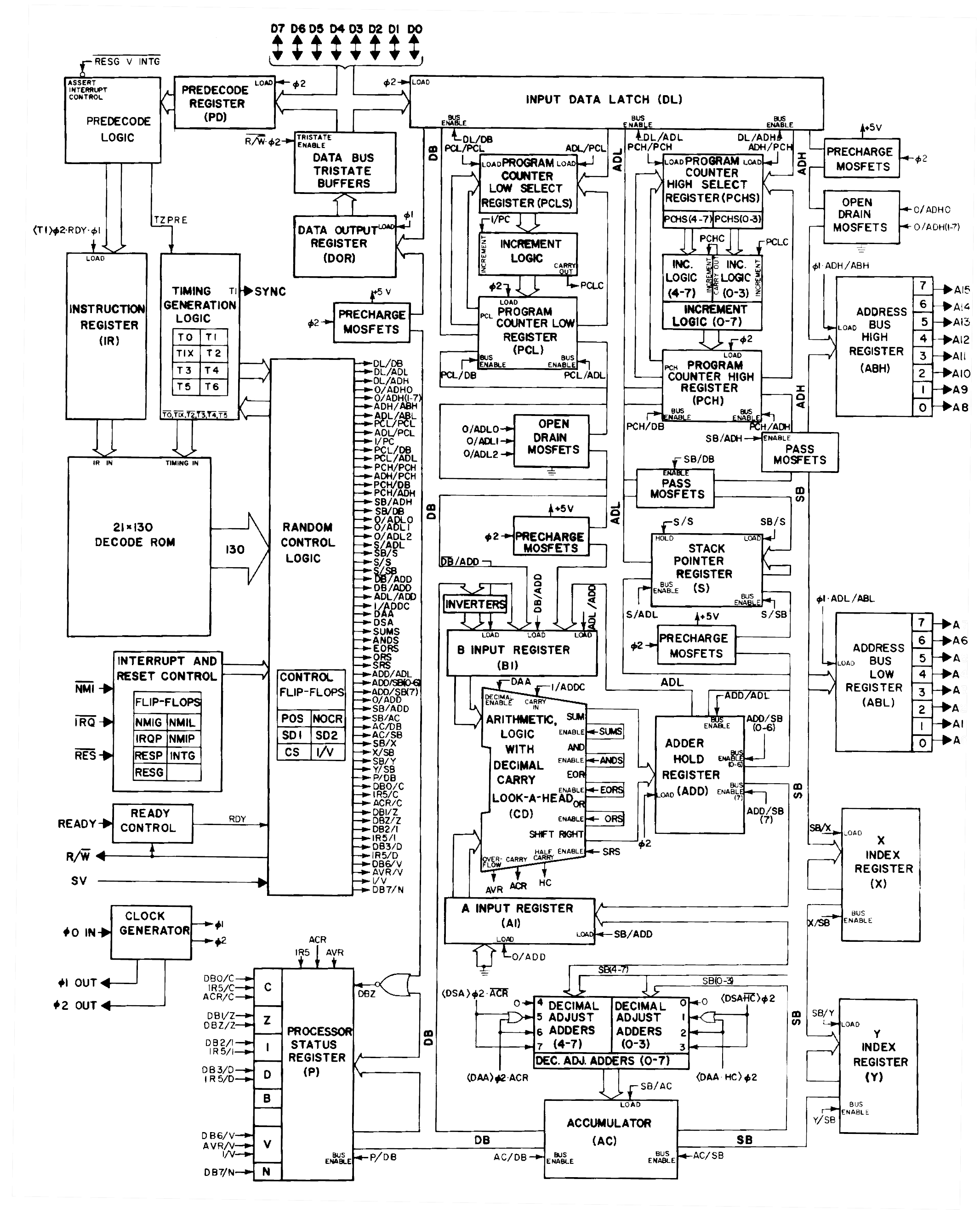
As for how data is valid at the rising edge of "M2", well the data output latch is enabled throughout "M1", but its tri-state buffer is enabled at "M2" && /RW (but /RW was predecoded through "M1".) With the propagation of input buffers, data arrives before/at the rising edge. Datasheets won't tell you this, but it can be observed by crosschecking the only accurate 6502 diagram:
http://www.weihenstephan.org/~michaste/ ... 2/6502.jpg with the schematic:
http://www.shiresoft.com/downloads/docs/6502.pdf .
I'll have to respectfully disagree about data on the rising edge of M2.
I'll use these as my sources:
http://www.atarimagazines.com/computeii/issue1/page9.php
Specifically, Figure. 1 and the paragraph below.
Datasheets, this one and the other ones on the 6502.org site.
http://6502.org/documents/datasheets/synertek/synertek_hardware_manual.pdf
I'm not sure why datasheets are not valid as they specifically say when devices can guarantee data to be valid from the CPU.
I hope others could respond as we could go back and forth on this forever.
Also, kathaku I wasn't talking about the CPLD not working. Just not working when the MMC1 load is in it. Try loading CPLD with the MMC1 code while using a non MMC1 game that doesn't use any kind of mapper chip. The game should still run correctly, right?[/url][/quote]
Okay here's a better waveform to look at. This is what I thought was a write to Reg0.

So if the data is ready on the rising edge of M2, then D7 is a 1, but if it's on the falling edge of M2, then D7 is a 0. I thought it would've been the falling edge, because on the rising edge D7 is always 1.
I could've made a mistake, when I get home tonight I'll try again.
2600 wrote:
I'm not sure why datasheets are not valid as they specifically say when devices can guarantee data to be valid from the CPU.
I'm not denying that it's most proper to use the falling edge, just pointing out that designs have had success with the rising edge. If data wasn't arriving in time, lots of designs out there wouldn't work, but they do. I don't think the PowerPak has any input delays on the line, but that would be the first thing to check in the constraints file.
I really think the datasheets should be taken with a few lumps of salt, they significantly oversimply the internal workings and the timing doesn't necessarily reflect the 2A03's process.
Quote:
we could go back and forth on this forever
Although I have yet to make this mapper work with my PLD, I have learned enough to know much more clearly what is going on. I figure the problem is now something that can be solved with some simulation.
Thanks to everyone who's helped me out with this - and when it
does work, I'll post my working code for all.
You know it is kinda interesting that you are having trouble with MMC1 on your board. The FunkyFlashCart had trouble with MMC1 as well. I don't think that was ever fixed though.
Good luck it will be interesting to see what you find.
I'd have to look up more detail of the mapper, but I wonder if you should clear q_s when the count is 5 as well. I also wonder if checking if count is = to 5 should be in a separate process and synchronize it to M2, but use the opposite M2 polarity of when you clock the data in. That way there would be a little delay to clock the data in correctly before you transfer it.
Quote:
prg_addr_out(17) <= R3(3) OR prg_addr_in(14);
prg_addr_out(16) <= R3(2) OR prg_addr_in(14);
prg_addr_out(15) <= R3(1) OR prg_addr_in(14);
prg_addr_out(14) <= R3(0) OR prg_addr_in(14);
What if you burn for example a PRG ROM that is 128KB of size
and the prg_addr_in(14) would be '1'?
It will make the cpu read at the place that it is not programmed.
The quote in MMC1 specification is that it must be the last bank - the last one that is burned on the ROM (or maybe you will be playing with grames with 256KB of PRGROM only?)
Just minute ago I succesfully ran version of MMC (I had some problems during last hours).
It is basically very similar to yours instead of the one thing that I mentioned.
The next difference is that I init the R0 with 01100 and R1,R2,R3 with 00000
I am not using variables.
krzysiobal wrote:
What if you burn for example a PRG ROM that is 128KB of size
and the prg_addr_in(14) would be '1'?
It will make the cpu read at the place that it is not programmed.
Ground unused upper address bits when soldering the memory to the board.
Or program the same data repeatedly until it fills the chip so that the upper bits of the address won't matter. If you're not making a permanent cart (i.e. it's a devcart and you want to be able to run 256KB games as well as 128KB ones without hardware modifications), this is the better option.