bunnyboy wrote:
Bregalad wrote:
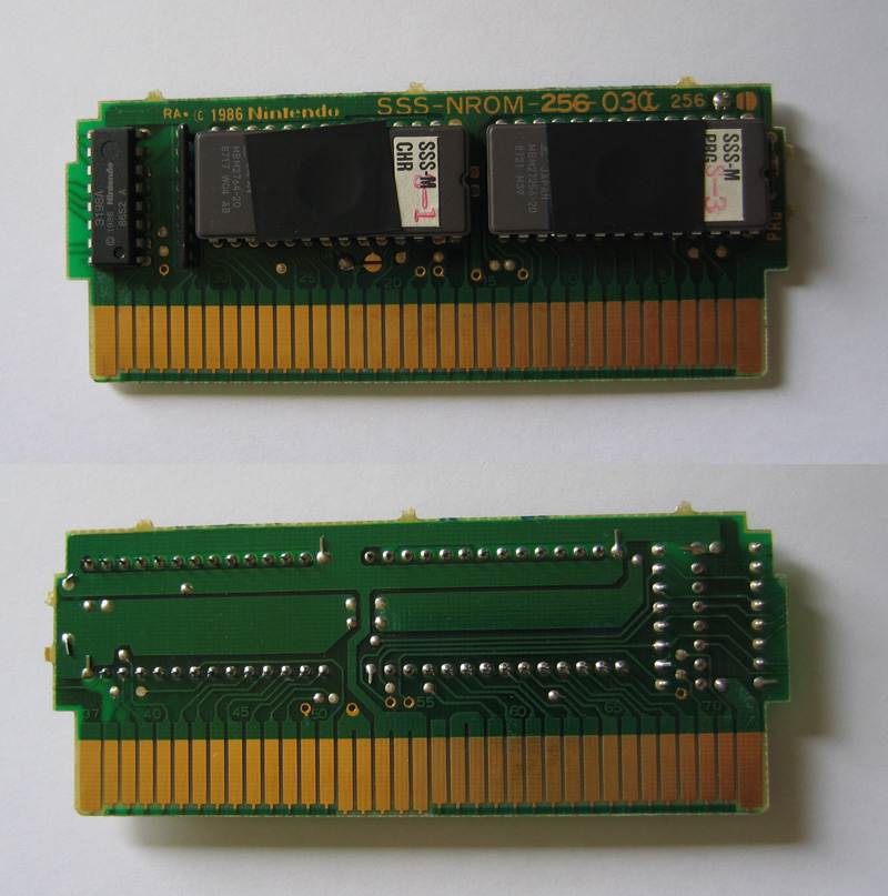
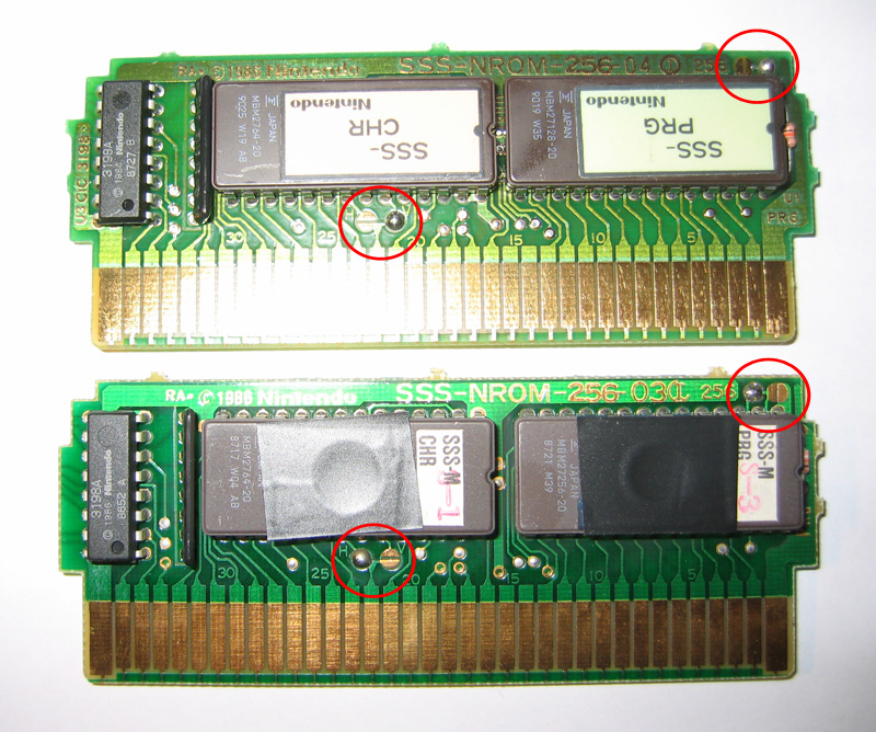
It obviously is mapper 0 (NROM board).
I am the only one who is intrigued by the resistor array on the CHR side, not present on regular NROM boards ?
Resistors are attached to extra lockout pins that are passed through the expansion port. Kev knows the details but the Famicom Box cic works a it different, possibly those are enable lines for the cic in each slot?
The 3198 lockout chip in the famicombox carts is kinda odd. The resistor network connects 4 lines from the expansion pins (on the cart) to 4 pins on the lockout chip.
Unlike the regular lockout chips, the 3198 is designed to work in a network of up to 16 lockout chips. Each of the 15 cart slots on the front + the menu board has a unique mapping of the 4 lines; pulled high or low depending on which slot it is in.
The master lockout chip on the main board has its 4 address lines connected to a latch which is written to by the CPU to select 1 of the 16 slaves on the various carts. The slave lockout chip matching the desired chip sent out by the master responds, while the other up to 15 chips do not.
This is how the system addresses each cart's lockout chip to see if a cart exists at that address.
On the regular lockout chips (3193, etc) those 4 pins are NC and don't appear to do anything at all.
The SSS boards are identical to their normal NES- boards except for the extra lockout chip pin routing; and nintendo was smart and used those normally useless pins that connected to the expansion port. There's nothing stopping you from dumping the SSS carts as NES-xxx models if you cut pin 4 of your lockout chip in the NES.
BTW the pin 4 trick works on the famicombox too, but I wouldn't do it- those lockout chips are pretty damn rare.
One more side note- the famicombox also contains a 3199 chip in it. This is not a lockout chip though, but is the coin timer. It will flash the screen when your time is about out, at the same rate that the NES' LED would flash