It must be one of the most useless question I've been asking, but this still bothers me.
The MMC2 does detect when the PPU reads from certain tiles ($fd and $fe) to active different CHR bankswitching latches. To detect those fetch, I think there should be a giant AND gate between all adress lines A6-A11, A12 (inverted for pattern table 0 and noninverted for pattern table 1), and A4 and A5 inverted or not depending on wich latch you want to activate. Since this must happen on all 8 scanlines the PPU is rendering the tile (i.e. the switching must happen when the tile is fetched, regardless if it's the top or the bottom of it). So then, A0-A3 should *not* be decoded, and if they were the switching wouldn't happen on the whole tile.
So then, I ask why those are connected to the MMC2 at all. Maybe they're just non connected internally ?
Also, since the chip does not map or watch anything in the CPU $0000-$7fff range, I really don't see why M2 is connected. Also, the chip has 2 ground pins.
Nintendo could then reduce pin cound to 34 pins without altering the chip's behaviour (however I don't know if there is anything between DIP-32 and DIP-40, but since they used that weird small-spaced DIP, why not use one with weird pin cound then ?).
I'll venture a guess and say that A0-A3 are used to distinguish between PPU rendering and $2007 accesses. If the PPU is rendering, then A0-A2 should remain constant and A3 toggle between 0 and 1 during the course of the CHR fetches. If $2007 were used, then A0-A2 would not be constant (if VRAM increment is 1) or A3 would not toggle (if VRAM increment is 32).
Quote:
If the PPU is rendering, then A0-A2 should remain constant and A3 toggle between 0 and 1 during the course of the CHR fetches.
For BG fetches, yeah. But definitely not for sprites fetches, unless you can make sure of this only with two ready (one with A3 at 0, then at 1 to validate the latch switch). And it'd be easy to bypass this by just reading $2007 twice with an increment of 1.
Also, I see no reason why manual $2007 reads would prevent the latches to be set to known state, since there is no other reason to read $2007 in the pattern table area. (I don't think games would just store dummy PRG data in the CHR chip and read it during VBlank, causing the latches go wrong. That would just be stupid).
I believe the logic is so that sprite switches happen only on the first scanline of the tile, while background switches happen on every scanline of the tile. From what I recall, the Japanese MMC2 patent document had a nice schematic of the entire CHR switching logic, and this is exactly what it did (specifically, it only used A0-A3 for one pattern table, but not the other).
Quote:
From what I recall, the Japanese MMC2 patent document had a nice schematic of the entire CHR switching logic
That doesn't help me much, since I've no acess to this (Google patent only include U.S. patents, and even if they had japanese one I'd understand nothing to them).
Quote:
and this is exactly what it did (specifically, it only used A0-A3 for one pattern table, but not the other).
Does it keep track of all $2000 writes to know wich pattern table is used for BG/Sprites (that would give a good reason to input M2 to the chip) ? Or does it try to determine wich of them is acessed from the previos/next PPU fetch to know if the tile was probably a BG or a sprite fetch ? Or does the chip just decode one line for tiles from a pattern table, and all lines for the other pattern table, assuming the game will put this to good use (like the MMC3 with its scanline counter) ? Does the same thing apply to MMC4 ?
EDIT : All few MMC2-MMC4 games I checked (wich is actually all ever made probably) used pattern table 0 for sprites and pattern table 1 for BG.
MMC2 doesn't "keep track" of anything in the sense of MMC5, it simply decodes two tile accesses, each decoding will select their corresponding register be to output. MMC4 works in the same fashion.
Bregalad wrote:
Or does the chip just decode one line for tiles from a pattern table, and all lines for the other pattern table, assuming the game will put this to good use (like the MMC3 with its scanline counter) ?
Presumably, this is how it works. Since both pattern tables have the same bank size, this doesn't present any real difficulty on the code side (with the MMC3, they added the extra bit to specify which one got two 2KBs and which one got four 1KBs).
Okay, this still bothers me a bit. I think I fully understand how nametable latches works. When a tile is encountered horizontally, it just change the VROM bank used for BG, and this has proved to be very usefull to have up to 512 tiles at one time on a single BG screen, especially for letters in textboxes. (Punchout does just do one change midframe, that could be done on any maper. However, it does this thing to show the opponant's graphics before the fight, and the MMC4 games uses this a lot).
But for sprites, I really don't see much usage of this, and the games I checked seems to no use sprite latch switching in an evident way as they do for BG.
The only way I know of that this mapper can effectively be used for sprites is if each on-screen sprite had two consecutive entries in OAM, the first using tile $FD or $FE and the second using the tile # for the sprite. This would ultimately result in only 4 sprites per line, although this can be improved if multiple sprites have the same Y coordinate and use the same CHR bank (those sprites would need to appear consecutively and have a single $FD/FE sprite preceding them).
Yeah, but if the mapper decodes only the first line of the tile, the only usage of this is standard midframe CHR switching, allowing the only advantage of avoiding boring timed code and sprite-zero hits. Also the sprite would be easier to hide, since it can be in a hidden area or just be blank, and the PPU will still fetch it resulting in a bankswitch (as opposed with sprite-zero hit where the sprite mustn't be blank).
If (as I understand it from this topic) Punch-Out!! severely underuses the MMC2, then how hard would it be to mapper-hack Punch-Out!! to, say, MMC3?
Actually what I said wasn't exact.
Punch-Out uses the MMC2 BG switching at title screen and all between-stage screen. MMC2 switching is almost not used on battle screen (only to switch screens between the actual fight area and the status bar/border of fight area and to show 'GET UP' when you get knocked out), and that is rather crazy since a sprite zero hit is used to change the horizontal BG scrolling, so why not use it to change the CHR bank as well ? Also, the game seems to rely on dummy name table/pattern table fetches to switch banks here. However, I'm pretty they could arrange tiles differently and use midframe bankswitching to bypass this.
MMC2 sprite switching is used before the fight, where the sprite banks alternate betwen the opponant's and the entrainer's (the hero is in BG), and since both does not overlapp only one sprite of each, $fd and $fe, is used at strategical position on the screen. Both sprites are totally transparent, and are in priority 0 and 1, so I think they could use sprite 0 for hit instead and switch sprite bank midframe using this.
The real mystery is that someimes sprites $fd and $fe are used on the opponant sprites on battle screen. At least Piston Honda has some $fe sprites on his animation frames.
My conculsion is that sprites can be used for bankswitching as well, but only their first row is taken care. Since sprite pattern fetching appear on the good order, on a gived scanline the priority of the sprites is more important that their position. So for several sprites sharing the same vertical position, it's possible to have one $fd sprites, up to 3 sprites from a bank, a $fe sprite and up to 3 sprites from another bank, and having them in any horizontal position will work. However, the latch will remain $fe for the 7 following scanline wich is plain STUPID ! This ruins all the advantage this technique could do.
Overall, Puch-Out does mainly waste MMC2's capacibilities, but it still use plenty of them everywhere (due to how it was designed), so it'd be quite hard to port the game to another mapper without rewriting the game core (arranging screens differently, etc...), but the game could get very similar graphics. Also, it's still worth noting the game was developped before the MMC3 was created, so it'd still have to rely on quite some raster effect to work with MMC1 (without talking about how PRG banks are organised).
Also, why M2 is connected to the chip is still a mystery, unless the chip decodes $2000 writes.
EDIT : Also, an interesting thing is that the MMC4 (so most probably the MMC2 too) does the switching AFTER the fetch. Punch-out and FC wars doesn't rely on this, but at least Fire Emblem relies on this on the right of textboxes. Some emulators (I don't remember wich ones) emulated the switching to take place just when the fetch is detected, making screwed up graphics in Fire Emblem. After all dvdmth was probably right on his first post, the lower adress lines are here to detect both pattern table fetches, then trigger the latch switching immediately after the second. And also I seriously doubt the complete adress is decoded for sprite and not for BG. Also I wonder how well $2007 reads have effect. None of those commercial games seems to read $2007 to set the latch in a known states, so no clue here.
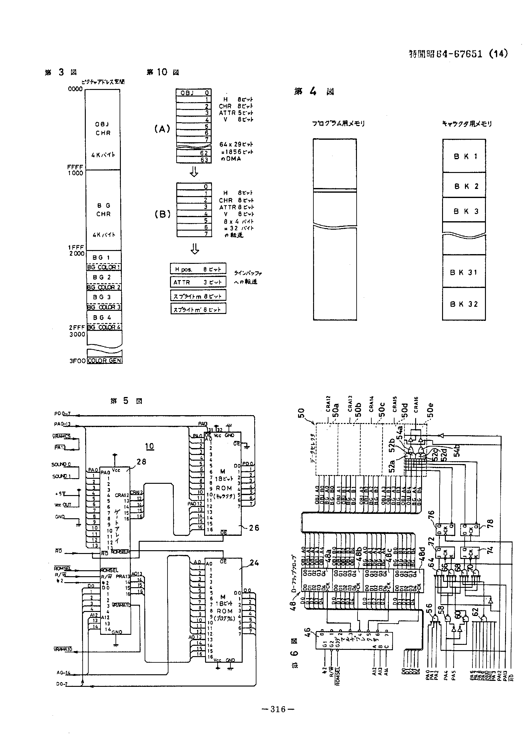
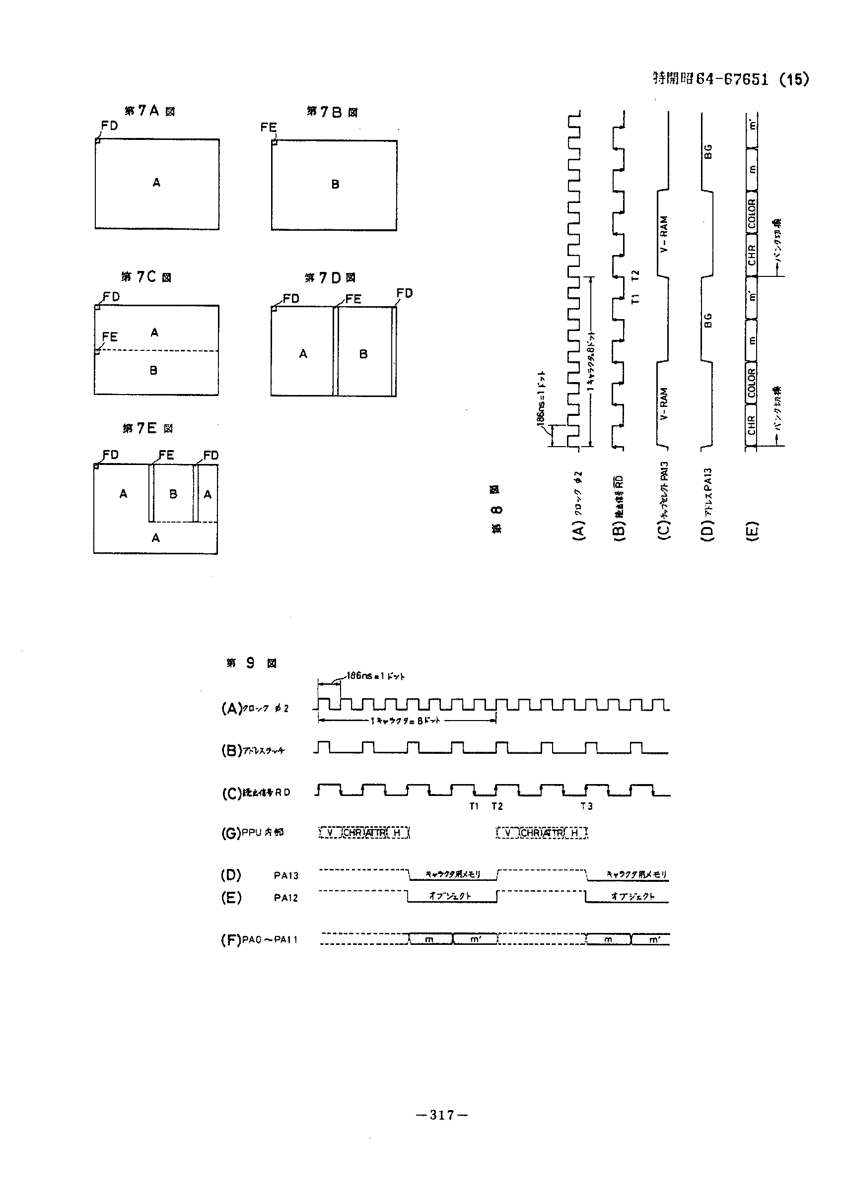
I've managed to dig up the MMC2 patent, and I've posted the last 2 pages (with the diagrams):
http://www.qmtpro.com/~nes/docs/mmc2pat1.png
http://www.qmtpro.com/~nes/docs/mmc2pat2.png
If you want the entire patent document, you can get it
here, though be warned that it'll take a while to download (it's about 800KB and the server isn't exactly on a fast connection).
Wow !!
It's so much a shame it's all in japanese !
The system seems to rely on a pulse on the read line to activate the latches.
A shematic on page 14 seems to proof that A0-A2 are used for fully decoding the adress only if A13 is low too. Also, this shematic show two flip flops in series, meaning that the actual latch will be actived after the second read, regardless if the second read is still in the $xfd0-$xfef section.
I wouldn't count on the patent being exact, the MMC1 patent was only similar to the actual logic. You should check out the Funkyflash implementation of PEROM if you want a working schematic.
I really doubt it'll be exact either.
What was the MMC1 issue ?
I don't remember; I think it may have had a bogus register and bad output logic.
The MMC1 patent described a mapper which took 7 writes in a row, such that 5 bits were data and 2 bits were address (i.e. register select). The real MMC1 takes 5 writes in a row, using A14 and A13 to select the register to update.
Hey, that is a fun thing to know. This could have been an idea to reduce pin count, but A13 and A14 are needed for bankswitching purposes anyway. Most likely Nintendo changed their design between the patent making and the final version of the chip getting manufactured.
But that would actually only change the interface, not the output logic in itself, unless this was wrong too.
Mattew J. Richard's MMC1 doccument, *supposed* to be the most accurate arround, has quite some annoyances. First he states that if one screen mirroring is used, bit 0 of reg 0 is wrong, while this isn't the case, it actually select wich screen is used (what is the point to get one screen mirroring if you cannot switch between screens ?).
Also, he explains the 32k bankswitching as being different banks number and a value shifted to the right, instead of being just the same bank numbers with bit 0 unused.
Bregalad wrote:
(what is the point to get one screen mirroring if you cannot switch between screens ?).
In a mapper where the only choices are map A, horizontal mirroring, and vertical mirroring, one can use map A for the scrolling screen and map B (which does not scroll) for a status bar.