Hello back guys
I just wanted to make a fresh topic so i don't get lost
Okay
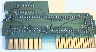
Now i Took the Nrom 128 from a Excite bike cart
I put 2 socket to it.
+ i put the wire from the front to the back
I got pics of it
I think i did okay
But i Did wire it once on a bad pin & it left a ''silver instead of gold on 2 pin...''
the 2 pin before the 5th one (wich i solder)...
Im worried but its maybe just the gold part gone & under it it's silver?
Im wondering if it will affect the contact or not:S....
BTW : is there a side where you need to put the eprom?
or is it like the sockets theres none?
here the pics
http://img355.imageshack.us/img355/3010 ... 002df9.jpg
http://img405.imageshack.us/img405/3769 ... 005uf3.jpg
[edited by Quietust - don't inline huge images]
hayabusafmw wrote:
But i Did wire it once on a bad pin & it left a ''silver instead of gold on 2 pin...''
the 2 pin before the 5th one (wich i solder)...
Im worried but its maybe just the gold part gone & under it it's silver?
Im wondering if it will affect the contact or not:S....
I think this is OK.
Quote:
BTW : is there a side where you need to put the eprom?
or is it like the sockets theres none?
Well, there are indentations in those sockets (the small semi-circles that are "missing"), but it seems you ignored them! =) Not that it matters for the sockets, they're there just to help you place the chips correctly.
According to your older pic (without the sockets), the indentations should be facing right. You installed the PRG socket correctly, but the CHR one is facing left. YOU DON'T HAVE TO DESOLDER THE SOCKETS AND SOLDER THEM AGAIN, just keep in mind that you soldered the socket facing the other way when inserting the CHR chip. When you do put the chips, make sure their indentations are facing right. Indentations on chips are usually small semi-circles.
Since each pin has a different function, it is essential that they're all pin is in the correct hole.
Thanks again tokumaru for your 2 replys
I am glad that i managed to do a good job on my first cart...
without messing it up you know this was my first time soldering.
I took a picture
to show you an example how i am supposed to put the chip
Let me know if i understood clearly .

It looks like your CHR ROM is plugged in backwards - I'm pretty sure pin #1 should be facing AWAY from the cart edge (i.e. upper-right corner). Then again, it could be due to poor picture quality - take a close-up shot of the board and crop off the table and the rest of the cart shell.
hayabusafmw wrote:
I am glad that i managed to do a good job on my first cart...
without messing it up you know this was my first time soldering.
You seem to have done a good job, but we'll only know when you try some games with it! =)
Quote:
I took a picture
to show you an example how i am supposed to put the chip
Sorry, but I can't tell from this picture which side the chips are facing. The top of the chips (the part with the small indentation) should be facing right (according to this picture). If they are, then that's correct.
EDIT: If Quietust is right, you put the chips as you installed the sockets (the CHR one has the indentation to the left). Your chips should be like this:
Code:
|||||||||||||| ||||||||||||||
-------------- --------------
| | | |
| CHR C | PRG C
| | | |
-------------- --------------
|||||||||||||| ||||||||||||||
The "C" is the indentation that marks the top of the chip.
tokumaru wrote:
The top of the chips (the part with the small identation) should be facing left (according to this picture). If they are, then that's correct.
Actually, no - the notches should be on the
right - see the picture in
this post.
Quietust wrote:
the notches should be on the
right - see the picture in
this post.
Oh yeah, sorry about that typo (I was thinking "right"...). Fixed now.
Don't plug it in like that! As noted above the notches go to the right. It will overheat and maybe damage the EPROM. I once plugged one in backwards and it did work after I let it cool down and plugged it in the right way.
Okay i changed the Rom i think that was Wrongly put in
Let me know if it seems ok now...?

tryed to make a close up from the left side view

Just realised : Toku left a diagram it didn't show up until i posted those pic
Your current setup looks good - unless you missed any modifications or have any bad solder joints on the sockets (or the EPROMs weren't programmed correctly), it should work properly.
Quietust wrote:
unless you missed any modifications or have any bad solder joints on the sockets (or the EPROMs weren't programmed correctly)
But we'll talk about that if it doesn't work when you try your ROMs. =)
Did you get your EPROM programmer yet?
Toku : Not yet
Still waiting for sivava's package Grrr...
it has been 2 week..
should be coming anytime soon.
By the way forgot to State
Is the CNROM games works on the Excitebike Dev cart i made?
because i got a 52 games cart at home that has
(muscle , legend of cage also on the same cart...& they are CNROM ) just checking.
i did received my 32 pin flash Eprom
So i could start to prepare my heavy shreddin MMC1 Cart
Put the 32 pin socket & 1 - 28 pin socket
but i was wondering
it's written on the board Nes sslrom - 05 U4MMC1
Will i need to make Wire job on that cart too aswell?
big thanks to all you guys!
hayabusafmw wrote:
Will i need to make Wire job on that cart too aswell?
Yes, you'll need to rewire, and a lot more wires than this NROM cart. You'll have to compare the pinout of your chip and the
pinout of the Nintendo ROMs to see what doesn't match.
I don't know what your Flash ROM is, but go to
this page and type in the name of your chip to get it's datasheet, which includes the pinout of the chip.
The pins that don't match will have to be rewired, and there are probably a lot of them, so it will look much more like my UOROM cart than your NROM cart! =)
If you have any doubts about the pins that don't match, just ask.
Alright thanks!
Ill study those page with the little knowledge i got & my broken english... grrr
By the way toku!
I understood for the chip
so the original nintendo (28 pin on the MMC1 cart i should of let it there since it's like a transfer chip.?)
but i did pull it out... & i think i broke a leg when i dropped it accidentally...
so is it a blank Chip that goes there? or still i will copy something there?
will go read on the Wiring pattern that i will need to do (to prepare myself mentally hehe)
found a page
someone that hacked a MMC1 cart
with a city moon patrol cart
this is his wiring.
I can see almost everything he did. i will check on the other site if the Pinout & wire are good (worked for him)
but just checking at least i found a reference (as im more visual)
I didn't find any SSLROM, but I found a
SLROM board, and it uses CHR-ROM, not RAM.
The 28-pin chip is the PRG chip.
So, you indeed have to remove both chips and install 2 sockets to turn it into a devcart.
great.
but i don't know this time is i need to bend a socket leg
or something special like this
because i have trouble reading charts
Im pretty confused
i understand a bit better but i wouldn't know like where to put a wire or not...
:S
If you want to use sockets be sure to do all the track cutting and wire slodering stuff BEFORE you solder the socket. This is needed between SLROM does not have standard ROM pinouts (as, say, SLEPROM would have), but industrial Nintendo pinout, so you need to turn it back to standard pinout. Info is available on Nesdev main page.
hayabusafmw, please read this message carefully. I'm sure you are able to understand this stuff, because you've been doing a good job so far, but you have to pay attention, in order to not get lost and ask the same thing over and over.
First, you have to understand the address lines and the data lines.
The address lines tell the chip the location of the data to be read from them. Address lines are identified by the letter "A" in pin diagrams. The larger the chip, the more address lines it has (because it has more addresses to access).
Rewiring address pins is simple: "A0" always connects to "A0", "A1" always connects to "A1" and so on. "A"s with the same number should be connected. If your chip has more address lines than the board, connect those to GND. This will happen when the chip you are using is larger than the board expects.
The data lines are always 8, because the NES is an 8-bit computer. The data pins are identified by the letter "D" or by "I/O" some times. You usually do not need to rewire those, as in most (if not all) chips these pins are at the same places.
Another pin that has more than one name is the "Vcc" pin. It can also be called "+5V". When rewiring, make sure that "Vcc" is connected to "+5V".
Some chips have "/CE" and "/OE" pins. They mean "Chip Enable" and "Output Enable". Just make sure these are connected to the holes with the same name.
Flash ROMs also have the "/WE" (Write Enable) pin. This is used only when programming the chip, and should be connected to "+5V" on devcarts.
That's about it.
EDIT: Bregalad mentioned "track cutting", something you probably haven't heard before. The thing is that you need to get each pin to the correct destination, and stop them from going to the wrong places.
Some people do it by cutting the tracks, some people do it by bending pins. I, for whatever reason, prefer to bend pins.
Both ways work, you are free to do what you feel is best. Cutting tracks can result in a cleaner job, with all the wires under the board.
Thanks Again Toku
Im trying to figure this
For me right now it's like all Chinese language ....
It's easy to just tell me do this do that put a wire here & there
but finding it on my own for now it's heavy
i will get around it maybe

All i know is i got heavy shreddin board MMC1 ( i want it to be more compatible with MMC1 games (almost all if possible )
Using At29c512 chips 32 pin
I checked the Pinout of the ''at29c512'' & compare it with a nes CHR ROM - 256KBytes (32pin)
Im trying to figure it all the best i can...
i feel dumb
hayabusafmw wrote:
It's easy to just tell me do this do that put a wire here & there
but finding it on my own for now it's heavy
Well, just try. If you have any questions, we'll help you out. Trust me, it's much better to know what you're doing than just have people telling you what to do, and blindly follow orders.
Quote:
All i know is i got heavy shreddin board MMC1 ( i want it to be more compatible with MMC1 games (almost all if possible )
If you use a SKROM, for example, you'll be able to run many MMC1 games, since it will also run SAROM, SBROM, SCROM, SEROM and SLROM games, possibly more. However, there is no easy way to have a board support both CHR-ROM and CHR-RAM. So, with your SLROM board, no Megaman 2, sorry. To run Megaman 2 you need a MMC1 board with CHR-RAM, such as SJROM, SGROM, SNROM...
Quote:
I checked the Pinout of the ''at29c512'' & compare it with a nes CHR ROM - 256KBytes (32pin)
Quote:
i feel dumb
You are not dumb, you just don't pay attention some times! Like above, when we told you that the "512" in your Flash ROM is in kilobits, so that's only 64 kilobytes. Not enough space to replace a 256 kilobytes chip, as you can see.
You have to use larger chips for this. Like I told you before, you should have bought some AT29C040, that hold up to 512KB, enough for
any NES game.
ahhh damn i didn't know for the chips i really tought it would gonna be ok
very confusing to put 512 at the end i always think 512K ah well..
I will try to ship them back to the person i bought them too..
but the 27c256 are they okay for my excite bike cart?
because if i made a silly error there too i will ship it back to him .
thanks again i will try to pay more attention
hayabusafmw wrote:
ahhh damn i didn't know for the chips i really tought it would gonna be ok
They're still good to use with NROM boards.
Quote:
very confusing to put 512 at the end i always think 512K ah well..
Well, it indeed is 512K, but it's K
bits, not K
bytes...
Quote:
I will try to ship them back to the person i bought them too..
If you can use the money to get some AT29C020 and AT29C040 that'd be great for you.
Quote:
but the 27c256 are they okay for my excite bike cart?
Yeah, thay are. But "27" chips are EPROMs, and you'll need UV light to erase them. Only EEPROMs and Flash ROMs can be erased by the programmer. I don't even know why anyone would want regular EPROMs anymore, with EEPROM and Flash avaliable.
Quote:
i will try to pay more attention
Yes, please. Also, try to read previous posts once in a while, looking for any information you might have missed. It is common that we do not understand something the first time we read it, but since you are learning more and more about this, a previous message that felt like it was in chinese might start making sense. It happens to me all the time when I'm learning stuff.
About AT29C040
I have asked him to trade the at29c512 vs AT29C040
I will have to see if my friend have it in stock
if not i will get refund & buy from futurlec
I bought Eprom Uv erasable because the 28 pin flash is no where to be found
like imposible to find
I bought a UV eraser that is on it's way
also because sometime i get old Game board that can have UV eprom that i can recuperate:)
thats the only reason
I will only Use 1 Excitebike cart anyways it's more a test for the first time so next will be only 32 pins (wich i will always use flash AT29C040) like you recommend.
thanks!!:)
Make a detailed diagram of the proposed modifications to the board and post it, so you can get some feedback. I found it helped to really study the available websites and the pinouts of the chips you are using. Then figure out the easiest way to rewire the board. Take it slowly and check for loose connections and unwanted connections at every step and then check again. Make lots of diagrams.
also be CERTAIN that you dump any old eproms that you reuse FIRST, who knows, if you find an old game board it could be something rare that the MAME or MESS team is missing... Just erasing the eproms like they're a consumable resource and ignoring what was on them is just plain stupid.
Got my eprom burner today
Just tryed burning Mario bros (cloud hack)
Burned the Chr once & i burned the ''prg'' twice because it didn't tell me it was full ....
should i burn it until they say me ?
Let me know
thanks!!:)
If the data is smaller than the chip, it's safer to replicate the data as many times as needed to fill the chip. How big is MB's program? 16KB? If so, just run the following command (of course, adjust the names of the files as needed): "copy /b mb.prg + mb.prg mb2.prg" at the command prompt (inside the folder where the files are, of course) to duplicate the program data.
You'd better do this to the CHR file too, but since it is probably 8KB, you have to copy it 4 times ("copy /b mb.chr + mb.chr + mb.chr + mb.chr mb4.chr").
If you program the chips ok, just place them on your board and see if the game runs.
I burned it Manually 4 times for the chr & 2 times for the prg
Tryed it it doesn't work... hmmm
weird...
Quote:
If you use a SKROM, for example, you'll be able to run many MMC1 games, since it will also run SAROM, SBROM, SCROM, SEROM and SLROM games, possibly more.
Even if there is more CHRROM boards than CHRRAM boards, that doesn't mean that more games uses CHROM than CHRAM. There is quite a lot of SGROM and SNROM games released on the US, while only very few games uses SAROM, SBROM, etc... (however, SLROM seems VERY sucessfull).
Quote:
To run Megaman 2 you need a MMC1 board with CHR-RAM, such as SJROM, SGROM, SNROM...
Actually SJROM is with CHR-ROM (Kevtris and his stupid misspelings...)
But it's possible to switch from CHR-ROM to CHRRAM on a board. You have to desolder the CHRROM as usual, but rewire pins differently. All adresses and data can be merged as you want since it's a RAM chip (i.e. even if the adress and data lines on the chip have numbers, exchange any of them in hardware has no effect). It does have more /CE, /OE, etc..., instead of more adress pins. So be sure to wire them to power or ground as needed. 8kb SRAM chips (6264) are often 28-pins, so smaller than 32-pins EPROMs of SCROM, SLROM and SKROM, and the same size as 28-pins EPROMs of SAROM, SBROM, SFROM and SJROM.
There is also the infamous R/W pin that must be wired directly on the connector, as opposed to ROM chips that does ignore this signal, since they cannot be written to. This is the most boring thing about porting a CHROM board to CHRAM, added to quite some more work on rewiring and actually buying the RAM chip. Also the chip have to come in a large DIP 28 package, and quite some RAM chips come in a small DIP 28 package. CHRRAM boards by Nintendo were made in order to accept both formats, however CHRROM boards just accept large chips only.
Please, tell us exactly what you are doing.
What version of the software are you using?
Did you set the jumpers and switches correctly (using the sheet that came with the programmer and the information os screen)?
Did you select your chip in the software?
Does the software read back the chip and verifies that the data was programmed successfully? Mine does this after every write.
I'd guess it's not programming correctly. Please tell us how you set everything up and how you're using the software.
Now, if the software verifies the chip and it programmed OK, the problem is in the cart.
In order for us to debug this, you have to tell us exactly what you're doing.
Bregalad wrote:
All adresses and data can be merged as you want since it's a RAM chip (i.e. even if the adress and data lines on the chip have numbers, exchange any of them in hardware has no effect).
Heh. I never though about this, but you are right! It doesn't matter if these lines are all mixed up, bacause since it's RAM, what is written to a place will be read from that place! Hah! Just found this interesting...!
You can also do this in ROM if you switch the image to match the swapped pinout.
Ahh I forgot to mention
my error
it's ''The excitebike cart i am trying to burn''
28 pin dip (both chips)
Nrom board 128
I am using EPROM35 program
I choosed Eprom 27c256 in the menu
I hit load (chr ) or (prg)
then hit program chip then it goes to 100% & verifys...
this is what i did
The Schema for the DIP are in the software i did place them like in the Image
but i did try to ''burn it several time after it didn't work.....'' but each time it says it's ok .... (but isn't there a stop in a number of time i can burn it?..........)
seems like i can burn it for ever.
The 27C's are EPROMS, right? I never used EPROM's before, but I'm pretty sure you shouldn't be able to reprogram the chip before erasing it (with UV light).
Does the software actually tell you that the data was successfully written (after verifying)? If so, the problem must be in the cart.
yes it says it's ''ok...''
i checked the cart
I even Redid the socket with the Wire.... to be sure cause there was a bit of solder to 2 points that was touching so (it was making a bridge) still doesn't work.........
i have 2 other eprom i could try they are blank...
i will try them with excitebike or Ice hockey
Do you still have the (excitebike) ROMs you extracted from the board or you busted them along the way?
If you still got them, try plugging those in. If the game runs, your board is OK. I always tried the original game when I first started with NROM devcarts, to make sure I was doing it right.
i don'T have the ''eproms anymore or rom'' but i did try ie hockey same story....
I check the board the wire seems okay maybe it touches the circle but it doesn't go all the way trought .. (it's impossible to make it stand up.. or i would have broken the socket pin...
& on the PCB everything seems ok... nothing touching....
CHR PRG all facing right direction
Pushed down to the limit so... i dunno where to look
maybe my burner or the Chips im using.
but i would rather say ''cart or chip''
hayabusafmw wrote:
i don'T have the ''eproms anymore or rom'' but i did try ie hockey same story....
There clearly is a problem somewhere, and if the other games didn't work, "hockey" probably also wasn't going to.
Testing the board with the original game chip would be the best way to verify that all the contacs work after the installation of sockets.
Quote:
I check the board the wire seems okay maybe it touches the circle but it doesn't go all the way trought .. (it's impossible to make it stand up.. or i would have broken the socket pin...
Do you have a multimeter, to test all the contacts?
Quote:
& on the PCB everything seems ok... nothing touching....
CHR PRG all facing right direction
Pushed down to the limit so...
I don't think this is enough to make sure that the cart is ok.
What happened to the original excitebike? Did you damage the chips that bad that you can't try to use them somehow? At least the PRG chip, because even if the graphics are wrong, you'll be able to see that the game is running. Don't you have any other NROM cart you're willing to remove the chips? Just to test, and if you're careful, you can even return the chip later.
You gotta be patient to identify where the problem is. If you have no means of checking the contacts on the cart (one by one with a multimeter, or with some original game chips) it will be hard to tell where the problem is.
Maybe you could try posting a few screenshots of what you're doing with the software...?
I had a spare Excite bike
opened it up
Kept the 2 Original chips tryed it in the Nes didn't work...
stays on a Grey screen
I know how to make work a nes in 1 shot normally all my games work in 1 try....
then i retryed puttin the Excitebike chips onto it's board i just pulled them from without soldering.........
Get the same grey Screen.........HUh?...
Even if they are not soldered the contact is suposed to be 'done''
I am somewhat confused....
On my Dev cart i did damage 2 pin when i badly soldered the wire to the bad pin when unsoldered
the GOLD color Turned into Silver ''metal like color''
but i don't think it would cut the transmission?
Gold to silver = not working?... i really dunno...
besides that my socket legs aren't soldered together so no bridge or interference there....
Just to be sure
I took this new ''excite bike cart & did the same thing but this time i didn't miss pin 5 in the back''
Same thing occurs.............................
Dammit...
I put a miltimeter on Dc?
I was reading on every contact. even the wire i installed i guess it's good news....
as i don't know much about those either...
i really dunno why the chips inside are the original Excitebike.....
hayabusafmw wrote:
Kept the 2 Original chips tryed it in the Nes didn't work...
You mean you tried the chips from another Excitebike cart? And it didn't work?
Quote:
then i retryed puttin the Excitebike chips onto it's board i just pulled them from without soldering.........
Get the same grey Screen.........HUh?...
Even if they are not soldered the contact is suposed to be 'done''
I don't think the chip would make good contact if not soldered...! Unless using a socket, of course, but as I understand you are not using one, just returning the chips to the board they came from, right?
Quote:
Gold to silver = not working?... i really dunno...
I don't think that this would damage the connection, but
even if it did, this wouldn't matter for Excitebike. Remember that Excitebike is a 16KB game? Remember that you put that wire to handle 32KB games? That contact means nothing to 16KB games, so this is not the case.
Quote:
I took this new ''excite bike cart & did the same thing but this time i didn't miss pin 5 in the back''
Same thing occurs.............................
Well, if even the original chip doesn't work, the problem is most likely with your soldering job.
Are you being really careful when handling those boards? There is a chance that you're damaging the traces on the board if you are too brute when doing the job...
Quote:
I was reading on every contact. even the wire i installed i guess it's good news....
With the chip pluged in, check for contact of each leg with the correspondent pin on the cart edge. Use that diagram of the NES connector and check if all the address and data lines are successfully connected to the chip. But really, check the chip itself, not the socket or the ball of solder under the board.
If each leg successfully reaches the cart edge, I can't see what's wrong. If any doesn't, you'll find where the problem is. Take some time to verify all the pins.
how i solder is turn the board upside down & solder the ''round'' with the pin coming out
I put not much solder but at least it stays on it...
But i am not that brute..
with the pcb...
& also near where the socket legs are coming out the ''top part doesn't have any trace at all
the bottom is the most carefull since you have the trace that goes to the pins... wich i taped all around so i didn't get any suprise this time....
I really dunno what i did wrong..
Maybe it's a lack of solder......
but that wouldn't make sens since they are in socket & it's hard as steel & the chips are pushed like to the point of never coming out (figure of speech)
Im gonna post pics of my work ..
PS:
i found out that my Socket legs doesn't have all ''solder to the circle some do some dont like the solder didn't pass from the bottom to Up ....
i don't know if it would affect it .. if yes tomorrow i will Put more solder until it fills the Complete hole... up the the socket...
http://img219.imageshack.us/img219/4618/pcb5ha3.jpg
this time i Broke the Leg instead of bending it so i was left only with a tiny metal circle so it doesn't touch the board at all ....
http://img482.imageshack.us/img482/2672/pcb6oe6.jpg
(yes the PRG chip is on the wrong side i just put them in fast for a pic)
[Edited by Quietust: I repeat, do
not inline huge images!]
hayabusafmw wrote:
Maybe it's a lack of solder......
but that wouldn't make sens since they are in socket & it's hard as steel
Even if not all the pins are really secure this could still happen. The only way to know for sure is checking each pin with a multimeter.
Quote:
& the chips are pushed like to the point of never coming out (figure of speech)
Just a note: you might want to try something that Memblers taught me: put a socket also on each chip, so that you don't risk damaging the chip when inserting and removing them. If you damage a socket, just replace it. I have been doing this ever since, and all my chips are perfect.
Quote:
Im gonna post pics of my work ..
Try to post some really close ones, and try to keep'em sharp, or it will not be possible to see anything. I doubt that would help much though, as the only person that can check each contact is you... =)
hayabusafmw: please stop inlining 2048x1536 pixel, >1 megabyte images. Not all of us have huge displays and/or are on broadband internet connections.
Sorry i did that in a rush + i didn't check the settings
ill know next time..
Still trying to figure my problem out.
resoldered some of the legs i thought were not that great....
I tempt to say it's maybe that wire that is not good.
but still i would get something on the screen or?.
hayabusafmw wrote:
I tempt to say it's maybe that wire that is not good.
I can tell you (and I already did) that it's not the wire. The wire is there for an address line that isn't even used in Excitebike, so this game should run fine with the board even if there was something wrong about the wire.
GOOD NEWS!!
EXCITE BIKE BOOTED"!!!!
i even played 10 mins
but my Burned games are showing graphix problem ...
I need to check that
now it's a more fun trouble shoot than to look into the cart itself

hehe
just found the probleme i think
i checked ''compare verify'' my CHR files doesn't match at all ....
so i dunno what happened there but i will need to reburn those:)
thats it i beleive:)
Ah also :
I want to buy othe EPROMS
SIVAVA.com has W 29C040-12TI (DIP 32)
are they anygood??
let me know if so i will order them right away .
Or some other Note :
I will try to do this for my :Heavy shreddin
But i will need assitance to know which is wich....
I am not familar Yet with The names of the pin & where does the count start on each socket as for pin 1 to 28 or 1 to 32.
SLROM (mapper 1):
PRG socket:
Bend up pins 1, 2, 24, 30 and 31 (or cut tracks)
Solder pin 2 to hole 24 (A16)
Solder pin 24 to GND (OE)
Solder pin 30 to hole 1 (A17)
CHR socket:
Bend up pins 1, 2, 22, 24, 30 and 31 (or cut tracks)
Solder pin 2 to hole 24 (A16)
Solder pin 22 to hole 31 (CE or CHR /A13)
Solder pin 24 to hole 2 (OE or CHR /RD)
hayabusafmw wrote:
I want to buy othe EPROMS
SIVAVA.com has W 29C040-12TI (DIP 32)
are they anygood??
let me know if so i will order them right away .
Well dude, I've still got AM29F040B which is effectively the same. Might be cheaper shipping, definitely faster than from Thailand.
Thanks for the offer i would of bought your chips
but I got 4x AT29C040 32 pin Off ebay (tonight for 23$ shipped)
it will be shipped from like HK ...
but still price was good i was just browsing when i saw them
i have a question
How can i ''make my MMC1'' more compatible?
It's a Heavy shreddin cartridge (it's written MMC1) SLROM -05
i want to start the project.
Starting with the CHR (32 pin socket)
But i don't know where to find the correct info for that & which are the good solder points.
I found some today while searching but they tell which pin to bend but it doesn't tell me where they are ect..
But i am REALLY confused....
on one side i got a 32 pin (CHR) on the other side i got only 28 pins.....
I will need to fit a 32 there too since the games are like 128k...
there is 2 extra hole but they are filled with factory solder they are maybe Grounds...
hayabusafmw wrote:
on one side i got a 32 pin (CHR) on the other side i got only 28 pins.....
Yeah, that happens. 128KB PRG ROMs from Nintendo have 28 pins, while any programmable chip that size has 32 pins. 128KB CHR Nintendo ROMs on the other hand have 32 pins.
With my UOROM cart I had to remove the 28-pin chip and put my 32-pin one. In fact, the rewiring for the PRG chip in your MMC1 board could be almost exactly like mine (I think you can see it well from the pics I posted). The only difference would be A17, which I soldered to the small chip to the left so that I could use 256KB instead of just 128KB.
If you want only 128KB of PRG, you could do the exact same thing I did in my cart, but wiring that A17 to GND (the same place where A18 was connected). But if you want to use 256KB, which I believe the MMC1 supports, you'll have to check where in the MMC1 chip the A17 line is connected. Look at the pinout of the MMC1 chip to verify that.
I haven't tried replacing CHR ROMs yet, so I don't have anything ready for those.
great I will check your picture .
& do the same.
will i need to put a switch like you did?
Also , I bought those chip you recommended (at29c040 ) finally didn't mess it up
big thanks!
That kind of rewiring is only for the PRG chip, OK? CHR will most likely be different.
hayabusafmw wrote:
will i need to put a switch like you did?
No, the MMC1 has mirroring selection as part of it's functions. The switch is only needed in carts where mirroring is hardwired.
Quote:
Also , I bought those chip you recommended (at29c040 ) finally didn't mess it up
Yeah, these chips are great.
Quote:
big thanks!
You're welcome. =)
Great so i will do the same Wiring As your PRG socket? the one turned upside down.
Did you have 28 pin too? on your board?
let me know
cause i have 28 need to put a 32 pin socket so i guess ill have to bend the pins or think of something.
hayabusafmw wrote:
Great so i will do the same Wiring As your PRG socket? the one turned upside down.
I'm not sure what you mean by "upside down"... I know that the board I used has the chip in an unusual orientation, but the pinouts are the same as any regular board, so just keep the notch in sight to not be confused by the orientation.
Quote:
Did you have 28 pin too? on your board?
let me know
Yeah. If you take a good look at my pics, you'll see that the top of the socket is projected out of the board, because the original chip had only 28 pins.
Quote:
cause i have 28 need to put a 32 pin socket so i guess ill have to bend the pins or think of something.
In my cart, all the pins with wires are the ones bent up. All others are soldered normally. As you can see, 6 pins had to be rewired (but 2 of them use the same wire, the top 2 on the right). Your rewiring should be the same, only pin 30 (A17, the 3rd one from the top on the right) should be connected to ground (to support 128KB games) or to MMC1's A17 pin (to support 256KB games).
Note that when I say "top" I'm always talking about the top of the chip, the part with the notch, it has nothing to do with the orientation of the board or the pictures. Just to make it clear.
Before i start
I was wondering the 2 extra Pins on top i need to bend them since they Will prevent the others from entering?
I had also i worry since on the board there is 2 dots after the 28th pin &on top too after the 14th... they are probably gounds or other contacts ... i worry if the bent pins touches it will do a weird contact there??...
what should i do?
Look the picture. .


[/list]
SLROM board was designed to take both 128kb and 256kb mask ROMs.
On standard pinout EPROMs, both have the same pinout, exept that A17 is NC on 128kb EPROMs.
But for Nintendo roms, both have a weird pinout, and the number of pins was reducted on the 128kb mask ROM to reduce pin count ( /OE, P and VPP aren't needed, so they are removed, and with the additionnal NC pin, that makes 28 left !). Since the 256kb mas ROMs does need the A17 pin, there was no other solution but keep the thing in DIP-32.
In summary those unused pins are all to VCC exept one of them wich is A17, and is unused on 128k cards. Just remove the solder into them (bendindg up pins will work as well, but I'd avoid it for long-term mechanical issues). This don't affect much the way you must rewire the EPROM. You have to cut A17 line anyway, and to port it to the real A17 pin is needed only if your EPROM is 256k.
okay so basicly i should remove the 4 extra holes & put the 32 Pin socket into there?
right?
exept for the ''pins i need to bend or re wire
? if there is some on the first 2 ones...
PS: could you point me to A17 please
I wanna know exactly where it is
So the CHR is left intact?
no changes?
hayabusafmw wrote:
I had also i worry since on the board there is 2 dots after the 28th pin &on top too after the 14th... they are probably gounds or other contacts ... i worry if the bent pins touches it will do a weird contact there??...
I also alway worry about this. Usually, when soldering the socket, I temporarily put a piece of wire between pins across the chip, so that when I put the socket on the board it stays slightly raised (the plastic does not touch the board), and then no bent pin makes contact with the board. After the socket is soldered, I just pull the piece of wire out.
However, I don't know it that makes the socket somewhat unstable (since all the force applied when inserting a chip goes directly to the soldered pins). I've been able to insert and remove chips without anything ba hapenning so far...
Another option would be to cover the contacts with some isolating material, so that there is no problem if the bent pins touch it. Since I can't come up with a good material nor the ideal way to glue it to the board, I never tried this.
About the holes that are covered with solder, I don't know if there are any guaranties of what they actually are. If I were you, I'd check where they are connect before using them.
hayabusafmw wrote:
PS: could you point me to A17 please
This page has the pinout for the MMC1 chip (at the bottom). It says that A17 is pin number 4. The 29C040 has A17 on pin number 30. Just be sure to connect those together and it should work.
Quote:
So the CHR is left intact?
no changes?
Of course not! Have you compared the pinouts? The NES CHR chip is quite different from the 29C040...
Great
About the ''pins touching the board this time i was lucky they ddon't seem to touch it at all i raised it to the point of breaking almost....''
But i will try your rick next time
Here is what i got
Right ride : pin 1 & 2 soldered together
the 3rd< Soldered (this is the one going to A17 (MMC1 chip 4th pin i beleive? right?)
Left side : pin 1 & 2 bent pin with 1 wire each
Here is a picture:)
front & back
I put enought lenght of wire in case of..


theres a weird gloss on the 2nd pic it's not a burn on the pcb or something it's the flash
I did the connection to the A17 on the MMC1 Chip (24 pin)
4th leg
I made the connection in the back not on the front like you did either way works...
Now for the rest can i base myself on the same wiring as yours?
PS: i FOund the original CHR in my drawer it wasn't this one i smashed it was the prg!!!
Great! can i put this one in as a normal chip without socket?
hayabusafmw wrote:
I made the connection in the back not on the front like you did either way works...
Yeah, that's fine. I bent the pin up because I didn't know if it was connected to something else. It probably wasn't, as the MMC1 pin probably isn't either, but it wouldn't hurt to check.
Quote:
Now for the rest can i base myself on the same wiring as yours?
Yup.
Quote:
PS: i FOund the original CHR in my drawer it wasn't this one i smashed it was the prg!!!
The chip from the NROM cart or from the MMC1 cart?
Quote:
Great! can i put this one in as a normal chip without socket?
Did you understand why I didn't do anything to the CHR chip in my cart? That's because that board uses
CHR-RAM! Your board uses
CHR-ROM, if you keep the original chip all the games you put in the PRG chip will use the same graphic tiles of the original game! Of course you don't want that!
Please, hayabusafmw, I've talked to you about CHR-ROM and RAM so many times already, but it seems you don't listen. Please, pay attention.
CHR-RAM boards: don't touch the CHR chip;
CHR-ROM boards: if you want the graphics to look correct, you have remove this and install a socket correctly rewired for the chip you're gonna use;
Ah damn sorry again for making you repeat...
I didn't see the difference in Chr ram & the other one so im doomed again in wiring .
great then Bring it on!
hehe , so For now i finished almost the PRG...
I am clueless for the CHR part tho...
I check this?
http://www.raphnet.net/electronique/nes ... inouts.txt
& check for 256kb chr pinout?...
& then compare it to
http://www.futurlec.com/Memory/AT29C040.shtml?
Right?
hayabusafmw wrote:
so im doomed again in wiring .
Yeah. You'll get used to it.
Quote:
Yep.
Quote:
& check for 256kb chr pinout?...
I think the MMC1 only handles 128KB of CHR (it stops at CHR A16, there is no CHR A17).
Quote:
Yes. I can tell you in advance that both A17 and A18 should be connected to GND, since as I said above the MMC1 only handles 128KB of CHR.
I took a quick look at the pinouts and wrote this:
What is different:
Code:
PIN 040 NES
01 A18 +5V
02 A16 /OE
22 /CE GND
24 /OE A16
30 A17 +5V
31 /WE /CE
What to do about each pin:
01 - bend up and solder to GND (pin 16)
02 - bend up and solder to hole 24 (A16)
22 - bend up and solder to hole 31 (/CE)
24 - bend up and solder to hole 02 (/OE)
30 - bend up and solder to GND (pin 16)
31 - bend up and connect to +5V (maybe you can even connect it to pin 32, right above this one, without even using wires, just solder)
Note that I wrote this somewhat quickly, and I can't be sure if everything is correct. You should try to compare the pinouts yourself and see if you end up with the same results I did.
What I don't want is that you blindly follow my (quick) notes and then blame me if it doesn't work! =)
Great i will try to check this again to confirm
I take your word
i won't blame you but you know it much more than i will ever for now:)
Hmm i finished Wiring the '' prg ''
i tryed to put back the original roms
Note: i didn'T solder the socket for chr yet i just let it sit in with the 'original Chr chip''
& it didn't work....
1 thing i beleive is that the 2nd wire on the prg (left side) is connecting to the Blank hole of a already bent pin on the 3rd wire (right side )....
& i beleive it made contact up to the bent pin i will unsolder & resolder....
but i might done it wrong maybe i am at the wrong place.
hayabusafmw wrote:
Hmm i finished Wiring the '' prg ''
i tryed to put back the original roms
DON'T DO THIS! You just rewired it so that you could use a DIFFERENT chip! Since you modified the pin assignments, of course the old chip will not work anymore! This kind of test is only valid for NROM, when you don't relocate pins!
To try this you NEED to burn a MMC1 game on a
AT29C040, which is the chip you rewired the cart for!
my bad again... Grr i learn everyday!!!
I thought so to put a 28 in a 32 socket would feel weird & don't take the same.
thanks master Toku!!:)
Here is the pic for the prg
please notify me if anything is wrong

thanks!! for your time! & fast response
I finished Wiring CHR too
I checked your CHr plan Toku & it seemed alright
everything maked sens i rechecked to be sure
& all the place you note were on the spot.
I have found 2 UV 128 kb (that seem to have the same pinout as the 29c040 i will try them Later on with a mmc1 game.. of the same size)
On an other subject
I have tryed my Other DEV cart : Nrom
It worked!!! I am playing SMB at the moment!
your copying method worked like a charm...
I was wondering is there anychance to Make this board Read CNROM games?
please explain to me:)
Yes why no ect
i will know for future:)
Big thanks!
Hey! Sorry for not answering about the PRG wiring you did, but I'm having a bit of trouble understanding exactly what you did there... do you mind writing each step down (as I did for the CHR chip)?
hayabusafmw wrote:
I finished Wiring CHR too
Hope that works fine. I'd worry less about the CHR chip though, because most of the games will still run if it's wired incorrectly (but with scrambled graphics), but you can try to fix that. It is easier if you that at least the PRG socket is wired correctly.
Quote:
I have found 2 UV 128 kb (that seem to have the same pinout as the 29c040 i will try them Later on with a mmc1 game.. of the same size)
You just happened to find these chips lying around? XD
Well, if you say the pinouts are compatible with the 29C040, go for it!
Quote:
your copying method worked like a charm...
What copy method?
Quote:
I was wondering is there anychance to Make this board Read CNROM games?
Well it is possible, but it's not just a rewiring job. You'd have to get a 74HC161 chip (from some other cart or maybe even "lying around"

)
Here's how CNROM boards work. I think it wouldn't be hard to incorporate the 161 to a NROM board (although it would be hanging), but I hardly think it's worth the trouble. First because I don't remember any good CNROM games, and second, I wouldn't render a nice UNROM (for example) board useless by removing its 74HC161. I'd rather make a UNROM devcart instead.
I will Try to post pictures for the chr
About the ''eproms i had'' i found them on old PC mother boards
& stuff i had laying around
I don't do magic I wish i did heheheh
I have 2 identical 32 pin 128k (SST 29EE010)
But i can't seem to flash them
even with the UV eraser
It was written in the data sheet to flash them with that
but also i noticed there is no 29EE010 on the Willem program?
because i beleive the pinout seems the same of the At29c040 that i ordered
hayabusafmw wrote:
i found them on old PC mother boards
Ah... that makes sense.
Quote:
But i can't seem to flash them
even with the UV eraser
Hm... I'm looking at the
datasheet and its says this is an EEPROM, and it's erased by software, not UV.
But the pinout is indeed the same.
Quote:
but also i noticed there is no 29EE010 on the Willem program?
Since the pinout is the same, I wonder if it would work to try programming it as a 29C010... But I wouldn't try that, because although the pinouts are the same, the operations performed when writing data might not be. And I'm sure you don't want to fry the chips, or, much worse, the programmer.
Try to search the web for this chip and your EPROM programmer. Someone might have said something abou that.
Ah well i don't wanna risk it .
Im gonna Just wait my chip like a grown up
Well im pretty happy for my first Dev cart
Im posting the pics for you to tell me if i did okay for the MMC1 Chr socket.
& wiring.
like i said i recheck what you said & it seem to make sens & i compared again the pins like you told me to
& it was okay
there is 2 wire i needed to ''add an extention , solder an other peice of wire & put electrical tape''
Here is is.


Any wire will work but I like the wire-wrap wire from Radio Shack. It's nice and thin and the wire-wrap tool really helps make a neat job.
it's like heat shrink isn't it?
like hmm how do they call this.........
i think insulation?
It's called wire wrap. You can get it anywhere. Fairly small calibre insulated wire in spools. Very easy to use especially with the wire wrap tool.
well thanks next time i will use
(ill have some this week)
i will check my store ..
Im thinking if this Cart works good (hopes so)
im going to make a MMC3 cart next...
I found that wire that is isolated with some transparent material instead of plastic is far better. Just place the wire in you hole, and the heat will meal the isolation (without sinking), letting you solder the stuff confortably.
hey guys
on some other note:
I have received my ''order for 28 pin dip'' flash Eproms...
for my Nrom cart it's gonna be better than having Erasable eproms.
but i have no succes in writing , or formating them....
With my willem Eprom burner...
I don't know why .
also in the software i only see at29c256 (64) ..
mine are ( 32 )
anyone ?
anyone knows how to program those 29c256 flash chip i have no success still
Gee, I don't know... and I can't check it now because I don't have my programmer with me. But I'm pretty sure this chip required some jumper on the board to be changed...
Did they send you a sheet of paper? Somewhere it points to a jumper that has to be changed in order for 29C256's to work.
Please check the sheet looking for this... Maybe you didn't see it?
yeah i think i had a paper with it i just hope I didn't throw it away....
since it might of been loose on my desk & took it for trash
Ill check for it
Hmm Toku :
I found a game today MMC3 (finally MEGAMAN!!!! hehe)
Joking ...
it's indiana jones Temple of doom .
I wanted to ask you WIll i need to ''change both eprom this time or only Prg?''
just checking
I ordered 2 extra at29c040
so i will have 6 of them
I want to prepare this Cart before i get my chip so i will have So much to test to go nuts
thanks again i will keep you update if i find the sheet: )
Ohh also i totally forgot to ask you
Have you checked the pictures i Put not long ago about my MMC1 cart?
I tryed rad racer today
I had bad graphics on it ...
metroid the same Thing...
Broken graphics but i hear the music & can see items moving.....
I thing maybe it could be 1 bad wire i know maybe which it could be
could you check the PRG on your cart ( the right side first wire the one with 2 connections on the wire (where does it go exactly? a ground?)
I just unsolder my connection to make it connect into the third hole.. (wich was a bent pin (that would be Hole 28 of the PRG chip)
tell me if it's correct now...
I retryed it still broken graphic maybe it's the test chips im using ..
the 29ee010
let me know
thanks!
Just ran the first test on my 29f040 512kb
On my MMC1 Dev cart
the Sound is playing but all the graphic are messed up once again... i don't know where to look for the problem , that would be mostly a chr prob?
but still anything you would check first?
hayabusafmw wrote:
Just ran the first test on my 29f040 512kb
On my MMC1 Dev cart
Ah, so the new chips work then?
Quote:
the Sound is playing but all the graphic are messed up once again...
Well, if the program is running, the PRG socket is alright. And if the tiles are garbled, there certainly is a problem with the CHR socket. You'll have to check again all the rewiring work of the CHR socket.
Quote:
i don't know where to look for the problem , that would be mostly a chr prob?
I'd go back to comparing the pinouts, and rewrite the rewiring instructions. Then check if that matches to what was done.
The problem is definitely in one or more wires of the CHR socket. Double, tripple check it.
At least, having the PRG running correctly is more than half the job done, since if it didn't run correctly, you couldn't even know if the CHR part was OK.
before you replyed
I checked my chr tobe sure
Iw as right & you were right
2 of my wire were miss placed
so i changed it
boom Ninja gaiden booted but now....
Im facing an even more Weird problem (the graphic problem is coming after 5 mins of game play....)
then i just hit the cart on top of my nes & sometimes it comes back ........
sometime it just dies there... in broken graphics...
this is Really odd
I even changed the Cart so it doesn't move that much inside the case....
this is really weird it happens after a certain period of gaming time Or usually when i die....
it seems maybe to be the way i entered the cart in my nes....
by the way : Is the Chr-ram games compatible with the wires i installed?
like rad racer, metroid, megaman 2, ?
I recall you say no but someone then explain that it may be possible to be done.
hayabusafmw wrote:
(the graphic problem is coming after 5 mins of game play....)
Then it must be some contact thing... but this is already better than how it was before.
Quote:
Is the Chr-ram games compatible with the wires i installed?
Hm... normally, no. But maybe you can check the pinouts of a RAM chip (which you'll have to take from some other cart) and maybe it's not that different from the AT29C? If so, then maybe you could drop the RAM chip ther when playing CHR-RAM games.
However, the RAM chips need an extra pin that ROM chip's don't use, the write signal, that indicates that data is to be written. ROMs don't use it because they can't be written, of course.
So, you'd have to pick that signal from the cart's edge and connect it to the chip.
I haven't compared the pinouts yet, so I can't really tell if it would be possible to use the same cart for ROM and RAM.
BTW, as far as I know, the chip used for CHR-RAM is the same used for WRAM/SRAM, so you can pick those and use as CHR-RAM without problems.
EDIT: Thinking about it a bit more, I believe it would be possible to use the same cart for ROM and RAM. You'd have to place your RAM chip on a socket (permanently) and have wires between the RAM chip and the socket attached to it to make the pinouts of the socket compatible with the socket installed on the board.
Of course, since you'd have to get that extra write signal from the cart's edge, that would have to be permanently connected to you RAM-chip-socket-monster-thing, and when using ROM games that would be just hanging there.
So, it would not be a very elegant or simple thing to do, but I believe it would be possible.
ah i see.... ah well for not everything works...
on MMC1 games but like ninja gaiden....
thats pretty much the only cool game compatible.... grrr
but i will try to get an CHR-ram game anytime soon , So i will only need to rewire the prg just like i did for this one it's gonna be an easy task
now i want to ask about MMC3 If i take a Temple of doom cart will it be Restricted as the mmc1 cart if so i won't attempt this.
let me know .