After some testing and checking of Kaiser chips and boards I think it is a good time to sum up my current state of knowledge.
Chips
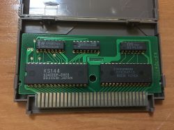
KS204
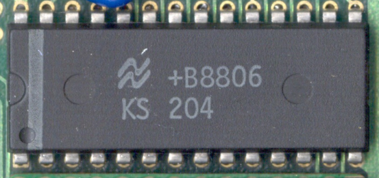
This chip can act either as simplified MMC3 or VRC2.
MMC3 mode:
* Enabled when M2 is high when chip is during RESET
* Chip behaves like simplified MMC3 (http://wiki.nesdev.com/w/index.php/INES_Mapper_206)
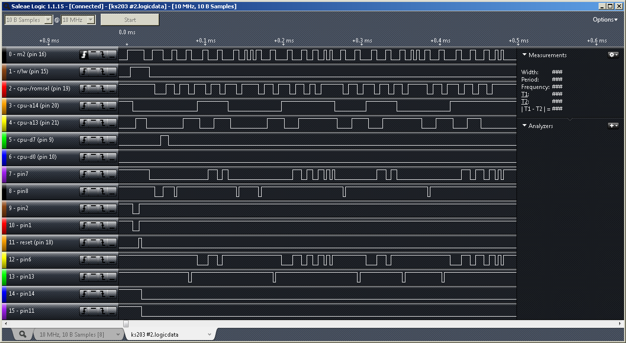
* Writes to internal regs occurs neither on falling edge of M2, rising edge of /ROMSEL, but on rising edge of its internal clock signal, for example:
* Metroid (FDS Conversion) (KS-7037) wired it a little differently and used only its PRG registers
VRC2 mode:
* Enabled when M2 is low when chip is during RESET
* During rising edge of M2, signals on pins 3-6 are latched internally as A14/A13/A12/A1
* During falling edge of M2, if /ROMSEL is 0 and R/W is 0 then a write to internal register occurs with
previously latched A14/A13/A12/A1 + current value of A0 + current values of pins3-6 (which are treaten as D3/D2/D1/D0)
* The value of pin 8 (D4) does not seem to have any influence on PRG/CHR/CIRAM operation (and there is no CHR-A18/PRG-A17), however Gyruss still wires it.
* Gyruss (FDS Conversion) (KS-7057) wired it differently and user only its CHR registers (for controlling PRG banks!)
* Contra J (KS-7049) probably used it in its natural way (that would explain presence of 74LS157 for muxing pins3-6 + 7432 for CHR /CE)
--------------------------------------------------------------------------------
KS203
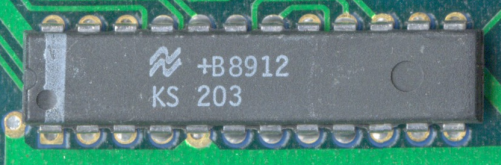
This chip can acts like MMC1. Further testing is required to see if there are any hidden functions.
* Rockman 2 - Dr Wily no Nazo (J) (KS-7061) used only its PRG registers
--------------------------------------------------------------------------------
KS202
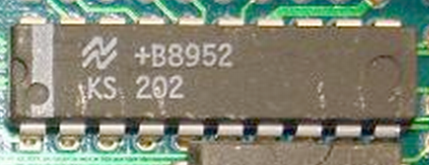
This chip acts like VRC3.
* Super Mario Bros 3 used it.
* Super Mario Bros 2 J - The Lost Levels used it.
* Salamander might use it
--------------------------------------------------------------------------------
Kaiser boards:
*KS-7010: Game: ?, Mapper: KS7010
*KS-7012: Game: Zanac (FDS Conversion), Mapper: KS7012 / 346
*KS-7013: Game: Highway Star, Mapper: KS7013 / 312
*KS-7016: Game: Exciting Basket (FDS Conersion), Mapper: KS7016 / 306
*KS-7017: Game: Almana no Kiseki (FDS Conversion), Mapper: KS7017 / 303
*KS-7021: Game: Contra , Mapper: 525
*KS-7030: Game: Doki Doki Panic (FDS Conversion), Mapper: KS7030 / 347
*KS-7031: Game: Dracula II: Noroi no Fūin (FDS Conversinon), Mapper: KS7031 / 305
*KS-7032: Game: Super Mario Bros 2 Lost Levels, Mapper: KS7032 / 142
*KS-7037: Game: Metroid (FDS Conversion), Mapper: KS7037 / 307
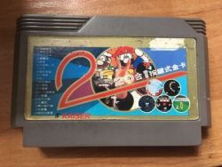
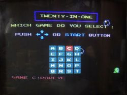
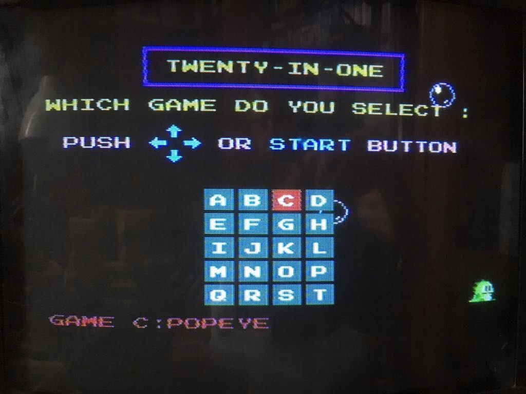
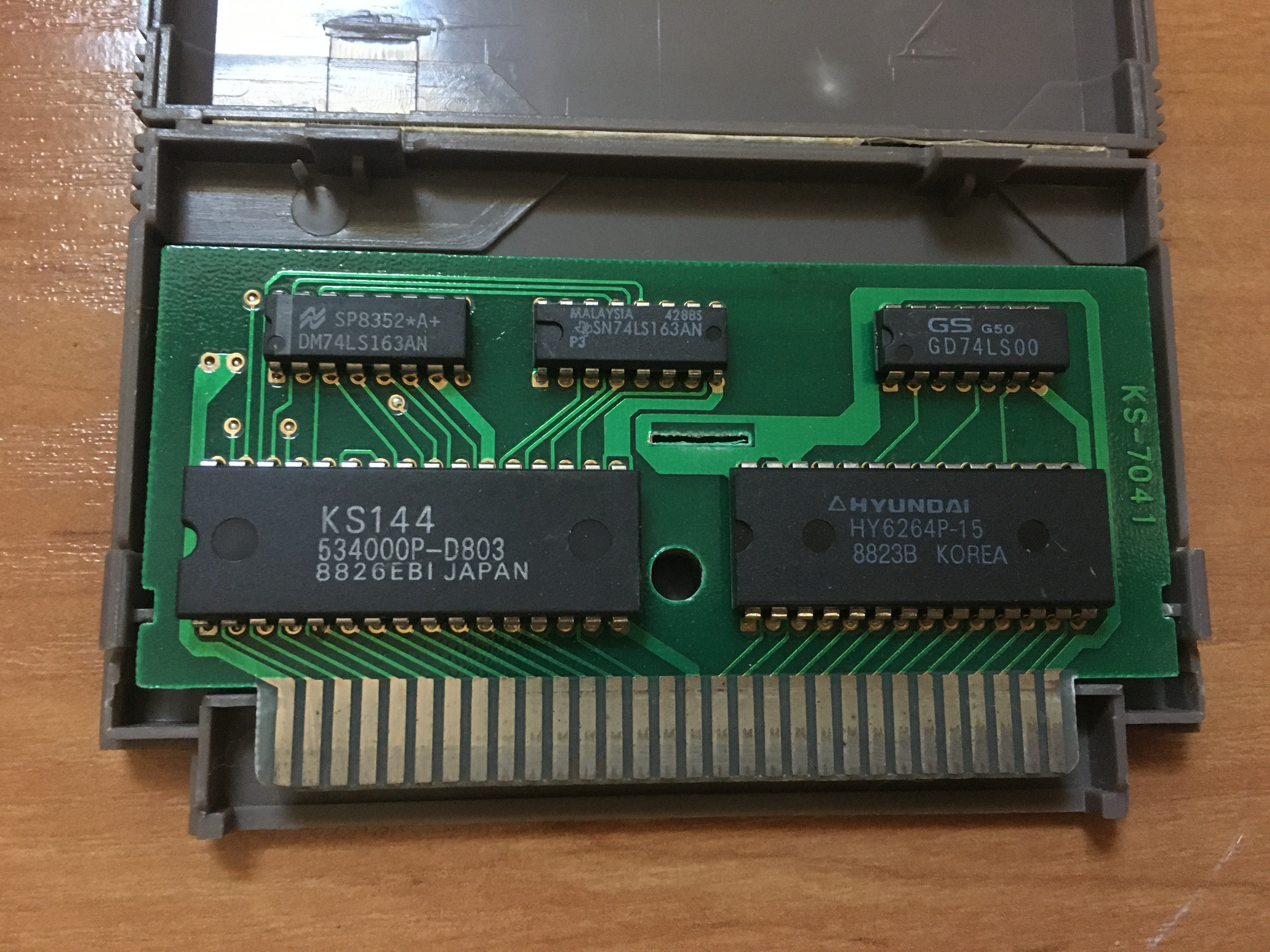
*KS-7041: Game: 20 in 1

*KS-7049: Game: Contra J, Mapper: 23
*KS-7057: Game: Gyruss (FDS Conversion), KS7057 / 302
*KS-7058: Game: ?, Mapper: 171
*KS-7061: Game: : Rockman 2 - Dr Wily no Nazo (J), Mapper: 1
Chips
KS204
Code:
.--\/--. .--\/--.
M2 -> |01 28| -- +5V M2 -> |01 28| -- +5V
R/W -> |02 27| <- RESET R/W -> |02 27| <- RESET
CPU A14 -> |03 26| <- CPU D3 CPU A14/D3 -> |03 26| -> CHR A16
CPU A13 -> |04 25| -> CHR A15 CPU A13/D2 -> |04 25| -> CHR A15
CPU D1 -> |05 24| -> CHR A14 CPU A12/D1 -> |05 24| -> CHR A14
CPU D0 -> |06 23| -> CHR A13 CPU A1 /D0 -> |06 23| -> CHR A13
/ROMSEL -> |07 22| -> CHR A12 /ROMSEL -> |07 22| -> CHR A12
CPU D4 -> |08 21| -> CHR A11 (unused) CPU D4 -> |08 21| -> CHR A11
CPU A0 -> |09 20| -> CHR A10 CPU A0 -> |09 20| -> CHR A10
PRG A16 <- |10 19| <- CPU D5 PRG A16 <- |10 19| -> CIR-A10
PRG A15 <- |11 18| <- PPU A12 PRG A15 <- |11 18| <- PPU A12
PRG A14 <- |12 17| <- PPU A11 PRG A14 <- |12 17| <- PPU A11
PRG A13 <- |13 16| <- PPU A10 PRG A13 <- |13 16| <- PPU A10
GND -- |14 15| <- CPU D2 GND -- |14 15| -> PRG /CE (0 when /ROMSEL=0 and R/W=1 else 1)
'------' '------'
KS 204 KS 204
in MMC3 mode in VRC2 mode
This chip can act either as simplified MMC3 or VRC2.
MMC3 mode:
* Enabled when M2 is high when chip is during RESET
* Chip behaves like simplified MMC3 (http://wiki.nesdev.com/w/index.php/INES_Mapper_206)
* Writes to internal regs occurs neither on falling edge of M2, rising edge of /ROMSEL, but on rising edge of its internal clock signal, for example:
Code:
CLK_8000 <= '0' when /ROMSEL = 0 and M2 = 1 and R/W = 0 and A1 = 0 and A14 = 0 and A13 = 0 else '1'
* Metroid (FDS Conversion) (KS-7037) wired it a little differently and used only its PRG registers
VRC2 mode:
* Enabled when M2 is low when chip is during RESET
* During rising edge of M2, signals on pins 3-6 are latched internally as A14/A13/A12/A1
* During falling edge of M2, if /ROMSEL is 0 and R/W is 0 then a write to internal register occurs with
previously latched A14/A13/A12/A1 + current value of A0 + current values of pins3-6 (which are treaten as D3/D2/D1/D0)
* The value of pin 8 (D4) does not seem to have any influence on PRG/CHR/CIRAM operation (and there is no CHR-A18/PRG-A17), however Gyruss still wires it.
* Gyruss (FDS Conversion) (KS-7057) wired it differently and user only its CHR registers (for controlling PRG banks!)
* Contra J (KS-7049) probably used it in its natural way (that would explain presence of 74LS157 for muxing pins3-6 + 7432 for CHR /CE)
--------------------------------------------------------------------------------
KS203
Code:
.--\/--.
PRG A17 <- |01 24| <- PPU A10
PRG A16 <- |02 23| <- PPU A11
PRG A15 <- |03 22| <- PPU A12
PRG A14 <- |04 21| <- CPU A13
VCC -- |05 20| <- CPU A14
PRG /CE <- |06 19| <- /ROMSEL
CHR A12 <- |07 18| <- RESET
CHR A13 <- |08 17| -- GND
CPU D7 -> |09 16| <- M2
CPU D0 -> |10 15| <- CPU R/W
CHR A16 <- |11 14| -> CHR A15
CIR A10 <- |12 13| -> CHR A14
'------'
KS 203
This chip can acts like MMC1. Further testing is required to see if there are any hidden functions.
* Rockman 2 - Dr Wily no Nazo (J) (KS-7061) used only its PRG registers
--------------------------------------------------------------------------------
KS202
Code:
.--\/--.
CPU-A12 -> |01 20| -> WRAM-/CE
CPU-A13 -> |02 19| <- CPU-D3
CPU-A14 -> |03 18| <- CPU-R/W
VCC -- |04 17| <- CPU-D0
M2 -> |05 16| <- CPU-D1
PRG-A14 <- |06 15| <- CPU-D2
PRG-A13 <- |07 14| -- GND
PRG-A15 <- |08 13| <- CPU-/ROMSEL
PRG-A16 <- |09 12| <- RESET
PRG-/CE <- |10 11| -> /IRQ
'------'
KS 202
CPU-A12 -> |01 20| -> WRAM-/CE
CPU-A13 -> |02 19| <- CPU-D3
CPU-A14 -> |03 18| <- CPU-R/W
VCC -- |04 17| <- CPU-D0
M2 -> |05 16| <- CPU-D1
PRG-A14 <- |06 15| <- CPU-D2
PRG-A13 <- |07 14| -- GND
PRG-A15 <- |08 13| <- CPU-/ROMSEL
PRG-A16 <- |09 12| <- RESET
PRG-/CE <- |10 11| -> /IRQ
'------'
KS 202
This chip acts like VRC3.
* Super Mario Bros 3 used it.
* Super Mario Bros 2 J - The Lost Levels used it.
* Salamander might use it
--------------------------------------------------------------------------------
Kaiser boards:
*KS-7010: Game: ?, Mapper: KS7010
*KS-7012: Game: Zanac (FDS Conversion), Mapper: KS7012 / 346
*KS-7013: Game: Highway Star, Mapper: KS7013 / 312
*KS-7016: Game: Exciting Basket (FDS Conersion), Mapper: KS7016 / 306
*KS-7017: Game: Almana no Kiseki (FDS Conversion), Mapper: KS7017 / 303
*KS-7021: Game: Contra , Mapper: 525
*KS-7030: Game: Doki Doki Panic (FDS Conversion), Mapper: KS7030 / 347
*KS-7031: Game: Dracula II: Noroi no Fūin (FDS Conversinon), Mapper: KS7031 / 305
*KS-7032: Game: Super Mario Bros 2 Lost Levels, Mapper: KS7032 / 142
*KS-7037: Game: Metroid (FDS Conversion), Mapper: KS7037 / 307
*KS-7041: Game: 20 in 1


*KS-7049: Game: Contra J, Mapper: 23
*KS-7057: Game: Gyruss (FDS Conversion), KS7057 / 302
*KS-7058: Game: ?, Mapper: 171
*KS-7061: Game: : Rockman 2 - Dr Wily no Nazo (J), Mapper: 1