I got my very own Famicom Network Adapter this weekend, which included the JRA-PAT game card and gigantic controller with numberpad. I verified everything works except obviously not able to dial into a Japanese horse racing dialup server. That still just cracks me up this was legitimately used for that.
Anyway, I have probed and prodded and found lots of curiosities. It is a big unknown what this thing is capable of, but here is what I have found so far.
Pinouts here for now:
https://wiki.nesdev.com/w/index.php/User:Ben_Boldt
The RF5C66 chip (U9):
The RF5A18 Chip (U10):
The JRA-PAT card:
Anyway, I have probed and prodded and found lots of curiosities. It is a big unknown what this thing is capable of, but here is what I have found so far.
Pinouts here for now:
https://wiki.nesdev.com/w/index.php/User:Ben_Boldt
The RF5C66 chip (U9):
- This seems to be a memory mapper chip.
- It can generate IRQs.
- It is connected to CPU address bits 0-7, 12-14, /ROMSEL, CPU R/W.
- It is connected to CPU data bus 0-7.
- The card has its own data bus. RF5C66 also connects to this data bus.
- (The card's address bus is directly connected to the CPU address bus however.)
- So it seems the RF5C66 must multiplex the CPU and Card data busses together.
- It controls what appears to be an 8kbyte PRG-RAM chip (U5) which is on the card data bus.
- It is connected to PPU A10 and A11 (and no other PPU address bits, no A12), so it isn't doing any fancy PPU stuff like MMC5.
- The presence of PPU A10 & A11 makes me think MMC3 scanline detection, but no A12 though.
- It is able to control or monitor the onboard CHR-RAM's /CE, not sure why. It does not receive PPU /RD or /WR.
- This chip has no means of writing to the onboard CHR-RAM and no access to PPU data bus.
- Has a 21.47727MHz crystal.
The RF5A18 Chip (U10):
- This appears to be a modem controller chip.
- It has its own private 8kbyte RAM chip (U6), presumably for buffering network data.
- It has CPU address bits A0, A1, and A2. No others.
- It is on the card data bus and not on the CPU data bus.
- It controls the LEDs.
- It reads the switch on the bottom of the network adapter.
- Has a 19.6608MHz crystal.
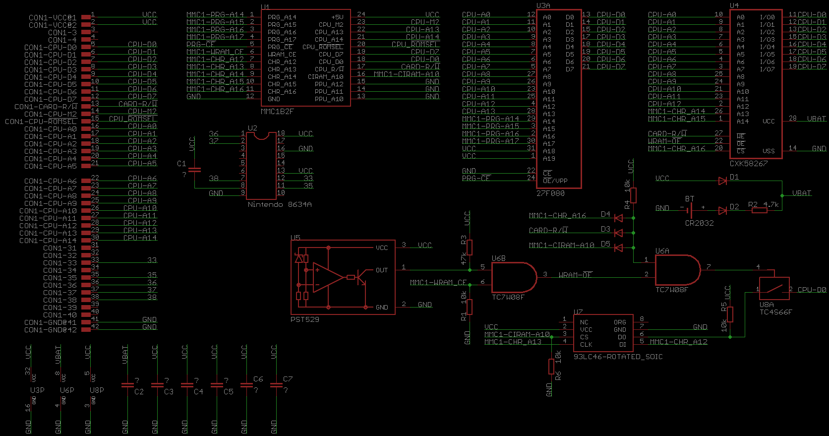
The JRA-PAT card:
- No CHR/PPU connections. The user program has to manually load data into CHR-RAM.
- The JRA-PAT card is not potted. I was reading somewhere earlier someone thought it was potted due to its weight. If you carefully peel the back metal piece off, it can be opened and accessed.
- The card is very reminiscent of a GameBoy cartridge. It is longer, but slightly thinner and skinnier.
- Contains an MMC1B2F mapper chip, SOIC-24 package.
- Contains a BR93C46AF, SOIC-8 package, which appears to be a 1kbit microwire EEPROM?? Not sure.
- It has a CIC chip scheme, using "8633AN" as the host CIC chip and "8634A" as the guest CIC chip inside the card. Great.

- The card itself is labeled with part# FCN-027, which matches the label on the ROM chip inside, so that makes me think it is a mask ROM and not an auto-destruct style RAM chip holding the program.
- The card has a battery in it. My battery is still 3V, so I don't actually know what happens when the battery dies.