I want to rebuild the DAC inside an Amstrad GX4000 videogame. The conversion in this system happens inside an IC which adds a noticable amout of blurriness to the picture so I'd like to replace the IC with an R2R-ladder. It's a 4-Bit-DAC, the video signals for Red, Green and Blue have 4 signal-lines labeled r0 to r3, g0 to g3 etc.
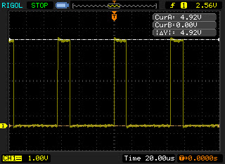
Here's what I see on the scope while the system is displaying a pure white screen on the input of the DAC-IC:

R0 to R3 all look the same.
The Vpp is 4.92V, I need to build the R2R-ladder with a maximum output-level of 0.7V, that would be the correct input level for the THS7314 that I'm going to use for amping the signals.
I've never build a DAC before, I understand its concept and the function of a voltage-devider but I need some help please to calculate the values for R and R2.
Also in an R2R there should be an opamp I guess, I'm pretty lost because I wouldn't know which one would be suitable for my application.
Any help with this is very much appreciated, thanks guys.
Here's what I see on the scope while the system is displaying a pure white screen on the input of the DAC-IC:

R0 to R3 all look the same.
The Vpp is 4.92V, I need to build the R2R-ladder with a maximum output-level of 0.7V, that would be the correct input level for the THS7314 that I'm going to use for amping the signals.
I've never build a DAC before, I understand its concept and the function of a voltage-devider but I need some help please to calculate the values for R and R2.
Also in an R2R there should be an opamp I guess, I'm pretty lost because I wouldn't know which one would be suitable for my application.
Any help with this is very much appreciated, thanks guys.