Some advice of DSP here...

This is an archive of a topic from NESdev BBS, taken in mid-October 2019 before a server upgrade.
View original topic
Some advice of DSP here...
by on (#149565)
As we know the NES generate sound at CPU cc freq, so if i have 44100 in my hardware i take it every 40.5~ so clocks.
I have been searching the web for info of sound filters, wich lead me to a bounch of DSP info wich i don't understand very well.

My question is: wich filter is the best for the best sound??
Re: Some advice of DSP here...
by on (#149567)
The best one to use is the one that you know how to implement :P

The simplest and wrongest way to generate audio is to just natively calculate everything at the target rate. This will produce ... passable, if lackluster, results. Pitches will be right, but there will be audible aliasing, and the higher frequencies on the noise channel will be wrong.

The simplest and not-wrong way is to generate the audio at the NES's native 1.79MHz, and use a sharp lowpass starting at ≈10kHz (such as a very long FIR filter, or some IIR filter like an elliptic, Chebychev, or Butterworth).

Slightly more complex is to generate the audio at the NES's native 1.79, and use a "decimating FIR lowpass filter".

Even more complex is do something like blargg's blip_buffer, which precalculates things such that it can natively generate audio at the target rate. Going into how it works is out of scope, for now.
Re: Some advice of DSP here...
by on (#149569)
lidnariq wrote:
Even more complex is do something like blargg's blip_buffer, which precalculates things such that it can natively generate audio at the target rate. Going into how it works is out of scope, for now.

Of course you don't have to understand how it works to be able to use it. Even if you're writing an emulator, you don't have to implement absolutely everything yourself. :)
Re: Some advice of DSP here...
by on (#149607)
lidnariq wrote:
The simplest and not-wrong way is to generate the audio at the NES's native 1.79MHz, and use a sharp lowpass starting at ≈10kHz (such as a very long FIR filter, or some IIR filter like an elliptic, Chebychev, or Butterworth).


I really suck about DSP. Any good advice/book/article/link to start with??
Re: Some advice of DSP here...
by on (#149609)
In fact, it all goes with the definition of "added value". Is there an added value to implement the audio resampling yourself? If you're genuinely interrested in DSP, then go ahead, you'll learn something. You have a neat and clever idea to test out? Go for it, maybe you'll find novel ways to do proper audio with good speed/accuracy. Otherwise, if you just want to get good audio from your emulator and spend time in things you think is more worth your time, then don't waste it uselessly and use a library that does it already (blip_buffer for instance).
Re: Some advice of DSP here...
by on (#149611)
Anes wrote:
I really suck about DSP. Any good advice/book/article/link to start with??

Did you try Bores?
Re: Some advice of DSP here...
by on (#149621)
Good source Tepples but i think i will use blip_buffer C code.

Now the problem is that i don't know even how to use the code. I took a look to the "demos" but it's greek for me.
What such a noob i am.

Any help?? at least a starting point.
Re: Some advice of DSP here...
by on (#149622)
Ok im totally lost, but i found a linear interpolation fn in wikipedia:

Code:
// Precise method which guarantees v = v1 when t = 1.
float lerp(float v0, float v1, float t) {
  return (1-t)*v0 + t*v1;
}


So i have 735 samples (NTSC) is it well to do a:
Code:
void linearinterpolation(float * src, int len, float * dest, int f)
{
   int i;
   float sample;
   for (i = 0; i < len - 1; i++)
   {
      sample = lerp(src[i], src[i+1], f);
      dest[i] = sample;
   }
}


I have the 735 buffer filled, and a "dest" buffer wich is then passed to directsound (of course there is an unsigned 16 bit conversion).

The sound plays, i think i don't hear any "better" sound and the worst is that there are some glitches.
Re: Some advice of DSP here...
by on (#149623)
What you're doing does not look like useful code. What is "f" supposed to do?

In audio, linear interpolation means that you are converting a buffer of one length into a buffer of another length (or alternatively, one speed/samplerate to another). It should look more like:

Code:
for (i = 0; i < len_out; ++i)
{
    // convert output position to input position
    float pos_in = float(i) * float(len_in) / float(len_out);
    // calculate blend value for linear interpolation
    float alpha = pos_in - floorf(pos_in);
    // find the two samples to interpolate
    int p0 = int(pos_in);
    int p1 = p0 + 1;
    dest[i] = lerp(src[p0], src[p1], alpha);
}


This isn't really optimal code, and it probably isn't even what you want to be doing, but I'm just trying to give an idea of what linear interpolation for resampling is. This technique is really only for upsampling, not downsampling.

If downsampling, you want something like a box filter. Basically take all the samples for a window of time in the input buffer, and average them together to make your output sample that represents that block of time (the samples at the beginning and end of the window will have reduced weight, since the window will probably begin and end partway through the sample).
Re: Some advice of DSP here...
by on (#149625)
rainwarrior wrote:
If downsampling, you want something like a box filter. Basically take all the samples for a window of time in the input buffer, and average them together to make your output sample that represents that block of time (the samples at the beginning and end of the window will have reduced weight, since the window will probably begin and end partway through the sample).


Ok, im learning thanks.

You say a "window of time", that's my 735 samples.

Quote:
Basically take all the samples for a window of time in the input buffer, and average them together to make your output sample that represents that block of time


Could you be more verbose about "average them together"??

Sorry being so noob.
Re: Some advice of DSP here...
by on (#149626)
The thing is that I CAN avarage 735 samples, so the sum of S0 + S1, +Sn divided by 735 leaves me with only one sample??
Re: Some advice of DSP here...
by on (#149627)
Anes wrote:
rainwarrior wrote:
take all the samples for a window of time in the input buffer, and average them together to make your output sample
You say a "window of time", that's my 735 samples.


No - your "window of time" is ~40.5844 samples (i.e. 1.79MHz divided by 44.1kHz).
Re: Some advice of DSP here...
by on (#149628)
So im doing it well becouse im averageting 40.5~ so clocks and then i divide the average var by that number.
The emu doesn't sounds bad, but compared to fceux or others is poor....
What does this emulators do to sound that way?? Is there any code/lib??
Re: Some advice of DSP here...
by on (#149634)
Emulators might use a simple FIR lowpass like a box filter, or some sort of big FIR, or some IIR, or the simplified version of blip buffer.
Re: Some advice of DSP here...
by on (#149635)
A box filter is a FIR filter, just a really simple one. Generically, a FIR filter is a window where each sample in the window gets a specific weight. You multiply each sample in the window by that weight, and add them together to get your result. In the box filter, every sample has the same weight.

Is there a practical IIR for resampling? (I've seen the analog equivalent in ADCs, but not in a digital resampler.)

The blip buffer also uses FIRs, but the process is inverted. Instead of generating the high-samplerate signal and then downsampling, it synthesizes the result at the target samplerate by replacing discrete steps with FIRs.
Re: Some advice of DSP here...
by on (#149637)
rainwarrior wrote:
A box filter is a FIR filter, just a really simple one. Generically, a FIR filter is a window where each sample in the window gets a specific weight. You multiply each sample in the window by that weight, and add them together to get your result. In the box filter, every sample has the same weight.


Im reading and reading from wikipedia and some things are unclear to me, for something quick, can't you post the code for this FIR filter?? Taking into acount my sample array is 41 samples.

thnks in advance.
Re: Some advice of DSP here...
by on (#149638)
http://ptolemy.eecs.berkeley.edu/eecs20 ... ation.html

Edit: sorry, this is just an example of a FIR filter without resampling, but the basic technique is the same. Multiply an array of input samples with the array of weights (FIR filter) and sum them up to produce an output sample.
Re: Some advice of DSP here...
by on (#149639)
Anything with full rejection in the stop band (e.g. Butterworth, Chebychev type 1) would work fine as an IIR resampling filter... Actually, anything where the stop-band is quiet enough such that aliasing from subsequent decimation wouldn't be audible would be fine too.

The real relative disadvantage comes from the ability to make FIR filters polyphase calculate only one phase of a decimating polyphase FIR filter, such that you can reduce the calculation load by the amount you're decimating the output.
Re: Some advice of DSP here...
by on (#149640)
rainwarrior wrote:
Is there a practical IIR for resampling?

Any low-pass IIR will do it. Clock in N samples and read only the output for the last one. The drawback is that you won't get linear phase, meaning some frequencies will be delayed slightly more than others.

lidnariq wrote:
The real relative disadvantage comes from the ability to make FIR filters polyphase

I thought IIRs could be polyphase too. If that's not possible, I'd like to see a citation so I can fix the encyclopedia article.

lidnariq wrote:
where you can reduce the calculation load by the amount you're decimating the output.

The blip-buffer technique likewise reduces calculation load.
Re: Some advice of DSP here...
by on (#149642)
tepples wrote:
I thought IIRs could be polyphase too. If that's not possible…
That was inaccurate terminology on my part. It's the ability to skip calculating some of the phases when decimating that makes the computational difference, which is only true when you have a set of poles at all of the roots that are a factor of the decimation ratio.
Re: Some advice of DSP here...
by on (#149650)
Looking back at the original post, if the goal is to improve the quality of your NES audio in a simple way, I might suggest what I did for the PC/Mac version of my Lizard game:

Generate audio at 4x the target samplerate (e.g. 192000 Hz), and downsample to the target samplerate just by averaging every 4 samples. It's very simple to implement, and 4x oversampling is enough to keep the quality pretty good, I think.

The one exception is the noise generator. The high frequency noise still sounds poor and un-NES-like without some additonal oversampling. I put an additional simple oversampling within the noise generation (i.e. to generate the noise output, I count up how many CPU clocks the noise is 1 vs 0 for this sample, then divide by number of clocks).


It's not as good as a more ideal filter, but it might be good enough for what you want. (You can listen to the PC build of Lizard to hear what it sounds like.) It's simple to implement, and relatively efficient.
Re: Some advice of DSP here...
by on (#149862)
The thing is that i suck at maths. When i find something on wikipedia it's full of formulas and such things that i don't understand. My math are high shool level.
Anyway i found a code of a guy implmenting a low pass filter and now sounds better, not "too much better" but better.

I preciate your help, but until i don't study well DSP and math im pretty screwed up.
Re: Some advice of DSP here...
by on (#149870)
Can (if it possible) somebody guide me how to use Blargg's blip buf:
As Blargg says:

Code:
The emulator merely sets the input clock rate and output sample rate, adds waveforms by specifying the clock times where their amplitude changes, then reads the resulting output samples.


- Is The imput clock rate: 1.73~mhz NES clocks??
- Output clock rate: is it 44100?
- clock times: what is this?
- where their amplitude changes: again, what is this??

I preciate such help.
Re: Some advice of DSP here...
by on (#149875)
Anes wrote:
- Is The imput clock rate: 1.73~mhz NES clocks??

Yes.

Quote:
- Output clock rate: is it 44100?

Usually either that or 48000.

Quote:
- clock times: what is this?
- where their amplitude changes: again, what is this??

Number of CPU cycles since frame start, or since power-on, I'm not sure.
Re: Some advice of DSP here...
by on (#149877)
I'd recommend 48000 as the default.

44100 Hz was the CD standard, and for a long time this (and simple divisions of it) was the standard samplerate for sound cards. It remains widely used for music media like MP3.

More recently, 48000 Hz has become the standard for most audio hardware. Gaming consoles, sound cards, blu-ray, etc. It's the most common native samplerate now.

A lot of sound cards support both. Some old sound cards don't support 48000, and some new sound cards don't support 44100. Often this is hidden from the user with a simple resampling at some layer of the software (operating system or elsewhere), but you can hear the conversion by testing high frequency signals for audible aliasing. You get the best sound at the card's native rate, so I'd recommend 48000 if you can't make it an option.
Re: Some advice of DSP here...
by on (#149887)
Ok im going to use 48000... but i simply give up about sound processing to sound better, i think i need more knowladge than i have.

Anyway thanks.
Re: Some advice of DSP here...
by on (#149960)
Sound cards are using 48KHz and its multiples since the introduction of AC97. 44.1 is resampled in software on cheap stuff or by hardware on less cheap stuff. Win Vista+ resample all stuff in software to whatever rate the sound card runs at (48KHz or a multiple).
Re: Some advice of DSP here...
by on (#149986)
rainwarrior wrote:
Is there a practical IIR for resampling? (I've seen the analog equivalent in ADCs, but not in a digital resampler.)

I use an IIR-based resampler in nemulator. I generate an audio sample every 3rd CPU cycle (~596600Hz), then filter it with a 16th order IIR lowpass (equivalent to ~512th order FIR). I then interpolate (3rd order b-spline) between samples for arbitrary sample rate conversion.

The IIR filter is implemented with SSE instructions and computes biquad sections in parallel. It's fast and cache-friendly.
Re: Some advice of DSP here...
by on (#150045)
James wrote:
rainwarrior wrote:
Is there a practical IIR for resampling? (I've seen the analog equivalent in ADCs, but not in a digital resampler.)

I use an IIR-based resampler in nemulator. I generate an audio sample every 3rd CPU cycle (~596600Hz), then filter it with a 16th order IIR lowpass (equivalent to ~512th order FIR). I then interpolate (3rd order b-spline) between samples for arbitrary sample rate conversion.

The IIR filter is implemented with SSE instructions and computes biquad sections in parallel. It's fast and cache-friendly.


Why every 3rd CPU cycle?

Also, is the b-spline step necessary? Once the high frequencies are filtered away, shouldn't you just be able to sub-sample the data (i.e. just throw away samples).
Re: Some advice of DSP here...
by on (#150048)
zeroone wrote:
Why every 3rd CPU cycle?

Probably someone's idea of the best compromise between speed and accuracy. I would have done every 2 CPU cycles, as the majority of the APU changes its output every other cycle, and the one channel that does allow odd periods (triangle) only changes it by a comparatively small amount.

Quote:
Also, is the b-spline step necessary? Once the high frequencies are filtered away, shouldn't you just be able to sub-sample the data (i.e. just throw away samples).

That'd be fine if 48 kHz divided evenly into the 315/176 MHz clock rate of the CPU. But it doesn't. There are 37.2869 CPU cycles for each output sample. So you end up having to interpolate when you decimate, inferring output samples that lie between the samples of the filter's output. You can use nearest-neighbor resampling, choosing (say) one output sample every 37, 37, 38, 37, 37, 37, 38, ... input samples, but it adds a bit of jitter. Linear interpolation shouldn't pose a problem though with this much margin.
Re: Some advice of DSP here...
by on (#150052)
tepples wrote:
zeroone wrote:
Why every 3rd CPU cycle?

Probably someone's idea of the best compromise between speed and accuracy. I would have done every 2 CPU cycles, as the majority of the APU changes its output every other cycle, and the one channel that does allow odd periods (triangle) only changes it by a comparatively small amount.

It's an optimization to reduce filter processing requirements. Every 3rd cycle is the most you can reduce it while guaranteeing that there won't be any aliasing of high frequencies into the audible range. re: 2 vs. 3, I don't hear any difference. Besides, does it matter? According to the sampling theorem, it should be fine, no?

tepples wrote:
Quote:
Also, is the b-spline step necessary? Once the high frequencies are filtered away, shouldn't you just be able to sub-sample the data (i.e. just throw away samples).

That'd be fine if 48 kHz divided evenly into the 315/176 MHz clock rate of the CPU. But it doesn't. There are 37.2869 CPU cycles for each output sample. So you end up having to interpolate when you decimate, inferring output samples that lie between the samples of the filter's output. You can use nearest-neighbor resampling, choosing (say) one output sample every 37, 37, 38, 37, 37, 37, 38, ... input samples, but it adds a bit of jitter. Linear interpolation shouldn't pose a problem though with this much margin.

The interpolation method was chosen based on the work in this paper: http://yehar.com/blog/wp-content/upload ... 8/deip.pdf. The signal is approximately 12x oversampled. According to the results in the paper (interpolation between the 8x and 16x numbers...), linear interpolation would result in ~50dB SNR, while 3rd order b-spline is ~106dB SNR.
Re: Some advice of DSP here...
by on (#150074)
James wrote:
tepples wrote:
zeroone wrote:
Why every 3rd CPU cycle?

Probably someone's idea of the best compromise between speed and accuracy. I would have done every 2 CPU cycles, as the majority of the APU changes its output every other cycle, and the one channel that does allow odd periods (triangle) only changes it by a comparatively small amount.

It's an optimization to reduce filter processing requirements. Every 3rd cycle is the most you can reduce it while guaranteeing that there won't be any aliasing of high frequencies into the audible range. re: 2 vs. 3, I don't hear any difference. Besides, does it matter? According to the sampling theorem, it should be fine, no?

Short-period noise at the highest frequency ($400E=$80) changes its output level every four cycles. (source) If you point-sample it every 3 cycles, then you'll pick up 1 of some levels and 2 of others. In sampling theorem terms, there's some ultrasonic aliasing that you're not completely rejecting. But I haven't tested sampling every 3 cycles, so I don't know either how it would sound. I chose 2 based on theory, as it's guaranteed to give equal weight to every output sample from square and noise.
Re: Some advice of DSP here...
by on (#150095)
I remember this discussion from the first time he mentioned it.

Decimating by 3 without filtering folds the frequency content from 597kHz±20kHz down over the audible range.

Noise rate 0 (highest frequency) produces a moderate amount of aliasing from that range: -11 to -13 dBFS; so does noise rate 1 (-17dbFS to -21dBFS). Noise rate 2 (-23dBFS to -29dBFS) and beyond don't alias too much...
Re: Some advice of DSP here...
by on (#150100)
lidnariq wrote:
Noise rate 0 (highest frequency) produces a moderate amount of aliasing from that range: -11 to -13 dBFS; so does noise rate 1 (-17dbFS to -21dBFS). Noise rate 2 (-23dBFS to -29dBFS) and beyond don't alias too much...

Noise rate 0 is ~447kHz. Wouldn't that be aliased to ~149kHz at Fs=596kHz? And noise rate 1 (~223kHz) shouldn't be aliased at all. Am I missing something?
Re: Some advice of DSP here...
by on (#150101)
The spectrum of the noise is quite broad:
Attachment:
4-sample-boxcar-FIR-spectrum-at-1789773Hz.png
4-sample-boxcar-FIR-spectrum-at-1789773Hz.png [ 3.94 KiB | Viewed 1779 times ]


So when you decimate by three, you fold the entire spectrum here into thirds:
Attachment:
File comment: The bend at ≈180kHz is because of the complex numbers producing constructive and destructive interference
decimated.png
decimated.png [ 3.54 KiB | Viewed 1779 times ]


Now, can we hear that aliasing as aliasing? I have no idea. I kinda bet the answer is no.
Re: Some advice of DSP here...
by on (#150104)
Where does the >447kHz content come from? Harmonics?
Re: Some advice of DSP here...
by on (#150112)
Take a discrete-time white noise source. LFSRs are white, so they produce equal energy at all frequencies. It sounds different from an impulse train because the phases differ from time period to time period.
( 1001 )

Define the sample rate to be the highest rate the APU generates, 447kHz. Now upsample by a factor of four to generate the CPU's "true" sample rate.
(Upsampling inserts zeros between each original sample. Upsampling also copies the spectrum, with reflection, so ABCD becomes ABCDDCBAABCDDCBA)
( 1000000000001000 )

All input magnitudes are still 1, even after upsampling.

Apply the four-sample FIR boxcar "sample-and-hold" filter. That multiplies by the spectrum in my previous post.
( 1111000000001111 )


This is true for all sample-and-hold filters ("boxcar" FIRs): they fail to filter out almost any harmonics.
Re: Some advice of DSP here...
by on (#150151)
James wrote:
rainwarrior wrote:
Is there a practical IIR for resampling? (I've seen the analog equivalent in ADCs, but not in a digital resampler.)

I use an IIR-based resampler in nemulator. I generate an audio sample every 3rd CPU cycle (~596600Hz), then filter it with a 16th order IIR lowpass (equivalent to ~512th order FIR). I then interpolate (3rd order b-spline) between samples for arbitrary sample rate conversion.

The IIR filter is implemented with SSE instructions and computes biquad sections in parallel. It's fast and cache-friendly.


Did you use a Butterworth filter? I read that high order, digital IIR filters require maintaining a large number of decimal places to avoid aliasing as a consequence of the feedback mechanism. Are you computing everything with 64-bit doubles? How CPU intensive is this process?
Re: Some advice of DSP here...
by on (#150155)
zeroone wrote:
James wrote:
rainwarrior wrote:
Is there a practical IIR for resampling? (I've seen the analog equivalent in ADCs, but not in a digital resampler.)

I use an IIR-based resampler in nemulator. I generate an audio sample every 3rd CPU cycle (~596600Hz), then filter it with a 16th order IIR lowpass (equivalent to ~512th order FIR). I then interpolate (3rd order b-spline) between samples for arbitrary sample rate conversion.

The IIR filter is implemented with SSE instructions and computes biquad sections in parallel. It's fast and cache-friendly.


Did you use a Butterworth filter? I read that high order, digital IIR filters require maintaining a large number of decimal places to avoid aliasing as a consequence of the feedback mechanism. Are you computing everything with 64-bit doubles? How CPU intensive is this process?


I use a 12th order Elliptic followed by a 4th order Butterworth. 32-bit single precision, no stability problems. It accounts for about 5% of the process' CPU utilization (which is ~8% on my 2.7GHz 2015 MacBook Pro).
Re: Some advice of DSP here...
by on (#150157)
James wrote:
I use a 12th order Elliptic followed by a 4th order Butterworth. 32-bit single precision, no stability problems. It accounts for about 5% of the process' CPU utilization (which is ~8% on my 2.7GHz 2015 MacBook Pro).


Why 2 filters? How did you test for stability problems?
Re: Some advice of DSP here...
by on (#150163)
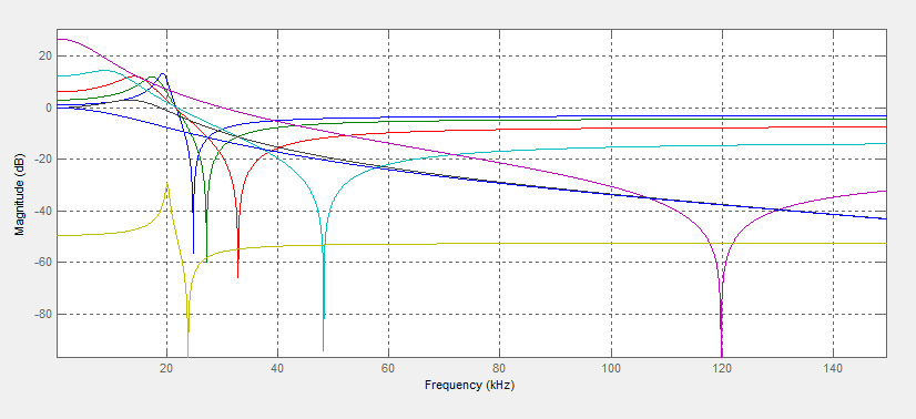
zeroone wrote:
James wrote:
I use a 12th order Elliptic followed by a 4th order Butterworth. 32-bit single precision, no stability problems. It accounts for about 5% of the process' CPU utilization (which is ~8% on my 2.7GHz 2015 MacBook Pro).


Why 2 filters? How did you test for stability problems?

The elliptic has a sharp cutoff, so I use it to kill frequencies > 20kHz. The Butterworth is used to more gently rolloff high (audible) frequencies.

re: stability - I designed it in Matlab, which will tell you if it's stable or not. It's not implemented as a single high-order filter (which would be unstable), but as a series of biquad filters.
Re: Some advice of DSP here...
by on (#150173)
I wonder if you can save any more CPU time by decimating the input somewhat between the elliptic and Butterworth stages, such as by providing only one out of every six outputs from elliptic to Butterworth.
Re: Some advice of DSP here...
by on (#150174)
tepples wrote:
I wonder if you can save any more CPU time by decimating the input somewhat between the elliptic and Butterworth stages, such as by providing only one out of every six outputs from elliptic to Butterworth.

My implementation is vectorized, so the Butterworth stage adds no additional CPU time. In general though, yes, you could do that.
Re: Some advice of DSP here...
by on (#150184)
James wrote:
tepples wrote:
I wonder if you can save any more CPU time by decimating the input somewhat between the elliptic and Butterworth stages, such as by providing only one out of every six outputs from elliptic to Butterworth.

My implementation is vectorized, so the Butterworth stage adds no additional CPU time. In general though, yes, you could do that.


Can you explain what you mean by "vectorized"?
Re: Some advice of DSP here...
by on (#150192)
I decided to give some of the ideas discussed in this thread a try. Below is a decimator implemented in Java. It uses a low-pass Butterworth filter to strip out frequencies above the Nyquist frequency (half the output sampling frequency) and it uses cubic splines to generate the output samples. Its constructor allows you to configure the input sampling frequency, the output sampling frequency and the filter order. This image shows its frequency response curve for an order 16 filter with an output sampling frequency of 48000 Hz. The decimator uses 64-bit doubles, providing a reasonable range of stability. And, timing tests suggest that it does not consume a lot of CPU.

Samples to be decimated are added at the input sampling frequency via the addInputSample() method. The processOutputSample() method of the DecimatorListener, which is passed into the constructor, is called back at the output sampling rate with the decimated samples.

Per the discussion on this thread, I recommend generating audio samples every 3 CPU cycles. I.e. for NTSC, the input sampling rate would be 19687500.0 / (3.0 * 11.0) and for PAL, it would be 53203425.0 / (3.0 * 32.0). Unfortunately, if you try a higher rate, such as every other CPU cycle or every CPU cycle, at a filter order of 16, the Butterworth filter becomes unstable. For the output sampling frequency, I suggest either 44100.0 or 48000.0. The filter order needs to be a base-2 number and as mentioned, certain combinations of these values will result in an unusable filter.

Code:
public class Decimator {
 
  private static final double I2 = 1.0 / 2.0;
  private static final double I3 = 1.0 / 3.0;
  private static final double I6 = 1.0 / 6.0;

  private final double[] inputSamples;
  private final double[] outputSamples;
  private final double[] A;
  private final double[] B;
  private final int lengthMask;
  private final int filterOrder;
  private final double cutoff;
  private final double inputSamplingPeriod;
  private final double ouputSamplingPeriod;
  private final DecimatorListener listener;
 
  private double time;
  private int index;
 
  // frequencies in Hz
  public Decimator(
      double inputSamplingFrequency,
      double outputSamplingFrequency,
      int filterOrder,
      DecimatorListener listener) {
       
    this.filterOrder = filterOrder;
    this.listener = listener;
   
    cutoff = outputSamplingFrequency / inputSamplingFrequency;
    inputSamplingPeriod = 1.0 / inputSamplingFrequency;
    ouputSamplingPeriod = 1.0 / outputSamplingFrequency;
   
    inputSamples = new double[filterOrder << 1];
    outputSamples = new double[inputSamples.length];
    lengthMask = inputSamples.length - 1;
   
    A = computeAs();
    B = computeBs();
  }
 
  public void addInputSample(double value) {
   
    inputSamples[index] = value;
   
    double outputSample = B[0] * value;
    for (int i = filterOrder; i >= 1; i--) {
      outputSample += B[i] * inputSamples[(index - i) & lengthMask]
          - A[i] * outputSamples[(index - i) & lengthMask];
    }   
    outputSamples[index] = outputSample;
   
    time += inputSamplingPeriod;
    if (time >= ouputSamplingPeriod) {
      listener.processOutputSample(computeSpline(
          1.0 - (time - ouputSamplingPeriod) / inputSamplingPeriod,
          outputSamples[(index - 3) & lengthMask],
          outputSamples[(index - 2) & lengthMask],
          outputSamples[(index - 1) & lengthMask],
          outputSamples[index]));
      time -= ouputSamplingPeriod;
    }
   
    index = (index + 1) & lengthMask;
  }
 
  private double computeSpline(double t, double y0, double y1, double y2,
      double y3) {
    double c0 = y1;
    double c1 = y2 - I3 * y0 - I2 * y1 - I6 * y3;
    double c2 = I2 * (y0 + y2) - y1;
    double c3 = I6 * (y3 - y0) + I2 * (y1 - y2);
    return ((c3 * t + c2) * t + c1) * t + c0;
  } 
 
  private double[] computeAs() {
       
    final double theta = Math.PI * cutoff;
    final double sinTheta = Math.sin(theta);
    final double cosTheta = Math.cos(theta);
   
    double[] binomials = new double[filterOrder << 1];   

    for (int i = filterOrder - 1; i >= 0; i--) {
      int i2 = i << 1;
      double poleAngle = Math.PI * (i2 + 1.0) / (filterOrder << 1);
      double sinPoleAngle = Math.sin(poleAngle);
      double cosPoleAngle = Math.cos(poleAngle);
      double v = 1.0 + sinTheta * sinPoleAngle;
      binomials[i2] = -cosTheta / v;
      binomials[i2 + 1] = -sinTheta * cosPoleAngle / v;
    }

    binomials = computeBinomials(binomials);   
    double[] as = new double[filterOrder + 1];
    as[0] = 1.0;
    as[1] = binomials[0];
    as[2] = binomials[2];
    for (int i = filterOrder; i >= 3; i--) {   
      as[i] = binomials[(i << 1) - 2];
    }

    return as;
  }
 
  private double[] computeBs() {
   
    final double[] bs = new double[filterOrder + 1];

    bs[0] = 1.0;
    bs[1] = filterOrder;

    for (int i = 2; i <= filterOrder >> 1; i++) {
      bs[i] = (filterOrder - i + 1) * bs[i - 1] / i;
      bs[filterOrder - i] = bs[i];
    }

    bs[filterOrder - 1] = filterOrder;
    bs[filterOrder] = 1;

    double scale = computeScale();

    for (int i = 0; i < bs.length; ++i) {
      bs[i] *= scale;
    }

    return bs;
  }
 
  private double computeScale() {
    double omega = Math.PI * cutoff;
    double sinOmega = Math.sin(omega);
    double poleAngle = Math.PI / (filterOrder << 1);

    double scale = 1.0;
    for (int i = (filterOrder >> 1) - 1; i >= 0; i--) {   
      scale *= 1.0 + sinOmega * Math.sin(((i << 1) + 1.0) * poleAngle);
    }

    omega /= 2.0;
    sinOmega = Math.sin(omega);
    if ((filterOrder & 1) == 1) {
      scale *= sinOmega + Math.cos(omega);
    }
    scale = Math.pow(sinOmega, filterOrder) / scale;

    return scale;
  } 
 
  private double[] computeBinomials(final double[] C) {
    final int N = C.length >> 1;
    final double[] D = new double[N << 1];

    for (int i = 0; i < N; i++) {
      int i2 = i << 1;
      for (int j = i; j > 0; j--) {
        int j2 = j << 1;
        D[j2] += C[i2] * D[j2 - 2] - C[i2 + 1] * D[j2 - 1];
        D[j2 + 1] += C[i2] * D[j2 - 1] + C[i2 + 1] * D[j2 - 2];
      }
      D[0] += C[i2];
      D[1] += C[i2 + 1];
    }

    return D;
  } 
}


Code:
public interface DecimatorListener {
  void processOutputSample(double sample);
}
Re: Some advice of DSP here...
by on (#150223)
I spent some time analyzing test signals tonight (square, triangle, and noise). Decimating before filtering does cause aliasing that is a) measurable in a spectrum analyzer and b) audible, particularly at higher frequencies. Decimating by 3 is especially bad.
Re: Some advice of DSP here...
by on (#150226)
I assume the aliasing is audible with tonal noise... is it audible when the LFSR's in full white noise mode?
Re: Some advice of DSP here...
by on (#150244)
James wrote:
I spent some time analyzing test signals tonight (square, triangle, and noise). Decimating before filtering does cause aliasing that is a) measurable in a spectrum analyzer and b) audible, particularly at higher frequencies. Decimating by 3 is especially bad.


Are you suggesting not to generate an audio sample every 3 CPU cycles?
Re: Some advice of DSP here...
by on (#150245)
I'm suggesting to generate a sample every 1 or 2 cycles. With 2 cycles, all aliases of square, even-period triangle, noise, and DMC will fold exactly on top of the actual frequencies. Aliasing from odd-period triangle and $4011 writes should be negligible and can be made even more so by using a 2-sample box filter before feeding those particular channels to your big brick wall.

Quote:
Unfortunately, if you try a higher rate, such as every other CPU cycle or every CPU cycle, at a filter order of 16, the Butterworth filter becomes unstable.

If every 2 cycles causes stability problems in the roll-off after your brick wall, use decimation between the brick wall and the roll-off.
Re: Some advice of DSP here...
by on (#150248)
zeroone wrote:
If every 2 cycles causes stability problems in the roll-off after your brick wall, use decimation between the brick wall and the roll-off.


The stability problems I referred to are a consequence of numerical accuracy. Discrete, high-order Butterworth filters require maintaining a lot of decimal places for certain cutoff frequencies. It's like a bifurcation event in chaos theory; the inaccuracies are rapidly magnified until you just get garbage out. I think that is why James only used a 4th order Butterworth filter and combined it with an Elliptic filter; he said he was able to do all the computations using only 32-bit precision, where as the 16th order Butterworth requires 64-bit.

Prior to experimenting with this filter, I was using a simple box filter and for the most part, it sounded just fine. For practically reasons, I may have to do what you suggested: putting a box filter or some other easy to compute filter in front of the Butterworth filter to try to get something out of all the available samples.

Edit: Another alternative is to use a lower order Butterworth and just apply it multiple times.

Edit 2: A 64-bit, 8th-order Butterworth filter remains stable for input sampling rates of 19687500.0 / 11.0 (NTSC) and 53203425.0 / 32.0 (PAL) and output sampling rates of 44100.0 or 48000.0. The filtering characteristics seem reasonable, but I do not have access to Matlab or any other special filter generating software; I wrote a test program that simply feeds the decimator with a slowly increasing frequency signal and it prints out the ratio of output-to-input gain. Timing still suggests that it should not eat up that much CPU, but I won't really know until I plug it into my emulator.
Re: Some advice of DSP here...
by on (#150274)
lidnariq wrote:
I assume the aliasing is audible with tonal noise... is it audible when the LFSR's in full white noise mode?

mode = 0? No. mode = 1, yes. Here's an example. Noise mode 1, period 5.

Not decimated
2x decimated

zeroone wrote:
I think that is why James only used a 4th order Butterworth filter and combined it with an Elliptic filter; he said he was able to do all the computations using only 32-bit precision, where as the 16th order Butterworth requires 64-bit.

You're correct in saying that a 16th order Butterworth would require double precision, but my decisions have nothing to do with stability, because...
zeroone wrote:
Edit: Another alternative is to use a lower order Butterworth and just apply it multiple times.

This is what I'm doing. A series of biquad filters. Matlab can convert higher order filters to second order sections. Looks like you can do it with Octave as well, but I've never tried.

Decimating by 2 is probably ok if you're short on CPU time. The only case where it's really audible -- with the signals I've tested -- is with high frequency mode 1 noise.
Re: Some advice of DSP here...
by on (#150280)
I plugged in my 8th-order Butterworth decimator and it does not eat up a lot of CPU. In fact, it should be possible to cascade a few of them together for a sharper drop-off.

But, at least to my ear, it does not sound significantly different from what I was doing originally, which was simply averaging together every ~37.287 samples together.

I am having issues with Namco 163 Audio. I can hear a sort of crackling noise in the introduction to Erika to Satoru no Yume Bouken. I assumed it was aliasing, a consequence of my simple sound sample averaging technique. But, nothing changed after plugging in the Butterworth decimator. My Namco 163 implementation averages together the enabled channels per the Wiki suggestion. But, I can still hear a crackling sound. I guess I must be doing something wrong there.
Re: Some advice of DSP here...
by on (#150281)
zeroone wrote:
But, at least to my ear, it does not sound significantly different from what I was doing originally, which was simply averaging together every ~37.287 samples together.
A 37-sample boxcar FIR has awful frequency rejection:
Attachment:
37-sample-boxcar-FIR-transfer-function.png
37-sample-boxcar-FIR-transfer-function.png [ 9.63 KiB | Viewed 1345 times ]


As a demonstration, try listening to a square wave at 9.4kHz with that implementation; there should be a pretty audible alias (-43dBFS) at 1kHz (from the 5th overtone).

Alternatively, try the tonal noise, which randomly (depending on the exact value of the LFSR when you switch from periodic to tonal) has either a VERY LOUD or completely absent 31st harmonic: [$400E] with $80-$82 should produce aliases from this overtone (i.e. above 24kHz, for 48kHz sample rate output)
Re: Some advice of DSP here...
by on (#150283)
lidnariq wrote:
As a demonstration, try listening to a square wave at 9.4kHz with that implementation; there should be a pretty audible alias (-43dBFS) at 1kHz (from the 5th overtone).

Alternatively, try the tonal noise, which randomly (depending on the exact value of the LFSR when you switch from periodic to tonal) has either a VERY LOUD or completely absent 31st harmonic: [$400E] with $80-$82 should produce aliases from this overtone (i.e. above 24kHz, for 48kHz sample rate output)


I'm sure you are right, but is there is a game I can try that will sound significantly different? It is possible that my hearing abilities are limited or that my cheap USB Logitech speakers are making these things indistinguishable. Or, my Butterworth filter may not be removing the right frequencies.
Re: Some advice of DSP here...
by on (#150285)
James wrote:
This is what I'm doing. A series of biquad filters.


And, this is what happens if you cascade 100 8th-order Butterworth filters with a cutoff frequency of 24000 Hz (red is the filter, blue is the cascade). Some gain is lost, a ringing appeared on the left and the drop-off slope did not increase all that much.
Re: Some advice of DSP here...
by on (#150288)
James wrote:
Here's an example. Noise mode 1, period 5.

Not decimated
2x decimated

It doesn't have a period 5. The shortest periods are 4, 8, 16, and 32. All periods in the LUT are even, in fact. Can you hear a difference between CPU and CPU/2 for any even period?
Re: Some advice of DSP here...
by on (#150293)
tepples wrote:
James wrote:
Here's an example. Noise mode 1, period 5.

Not decimated
2x decimated

It doesn't have a period 5. The shortest periods are 4, 8, 16, and 32. All periods in the LUT are even, in fact. Can you hear a difference between CPU and CPU/2 for any even period?

Good catch; my little test generator script wasn't using the lookup table :oops: Any even cases are fine.

So for the decimating by 2 case, that only leaves the triangle channel, and I can't hear any difference there. Any differences in the spectrum analysis are outside of audible range.
Re: Some advice of DSP here...
by on (#150294)
zeroone wrote:
James wrote:
This is what I'm doing. A series of biquad filters.


And, this is what happens if you cascade 100 8th-order Butterworth filters with a cutoff frequency of 24000 Hz (red is the filter, blue is the cascade). Some gain is lost, a ringing appeared on the left and the drop-off slope did not increase all that much.

You don't want to use the same filter for each section, though.

Here's the filter I (currently) use in nemulator. It's comprised of 8 biquad filters:
Image

And here's each individual biquad/section:
Image
Re: Some advice of DSP here...
by on (#150297)
Well, if you worked out all the filter constants, maybe I should just borrow them :) I thought you mentioned you used a Butterworth filter in there somewhere.
Re: Some advice of DSP here...
by on (#150307)
It looks like an elliptic brick wall followed by a Butterworth to hide some of the passband ripple. You can identify the Butterworth part in the overall gain plot as the gradual decrease 12 and 20 kHz. In the individual biquads plot, the two Butterworth biquads are those that don't cross down to -inf dB: dark green and lavender.

Popular IIR filter families from least sharp and most linear phase to most sharp and least linear phase:
  1. Bessel: as close to linear phase as possible, an IIR approximation of a Gaussian filter like that used in the S-DSP
  2. Butterworth: sharpest possible without ripple
  3. Chebyshev: ripple in either passband or stopband
  4. Elliptic: ripple in both passband and stopband

TIP: To simulate the speaker of a Game Boy, use a third-order (18 dB/octave) Butterworth highpass with a corner at 800 Hz. However, some design tools may not support odd orders, as Stephen Butterworth's paper introducing the concept of a maximally flat filter described only even orders.
Re: Some advice of DSP here...
by on (#150314)
How do you design a filter via cascading other filters?
Re: Some advice of DSP here...
by on (#150315)
The common IIR filter families are broken into second-order "biquad" sections, each of which has two poles and two zeroes. The output of each biquad is fed to the next biquad. It's like factoring a number into smaller primes for easier calculation.

As for cascading an elliptic with a Butterworth, this means you take the samples, pass them through the elliptic, and then pass the output of the elliptic through the Butterworth. This is called a "filter chain". And because biquads are linear, they commute, and I'm under the impression they can be processed in whatever order results in the least noise. This means you can decompose the elliptic and Butterworth filter into chains of biquad sections and then stick the biquads that form the Butterworth filter between the elliptic ones if you feel like it.
Re: Some advice of DSP here...
by on (#150317)
I follow. But, what's the approach of designing each filter, knowing that they will be cascaded?

Also, is an 8th-order Butterworth equivalent to 4 biquad sections? Could 2 cascaded Butterworth filters do the job of the 8 biquad sections? And, if that is the case, what target parameters would I need?
Re: Some advice of DSP here...
by on (#150318)
zeroone wrote:
I follow. But, what's the approach of designing each filter, knowing that they will be cascaded?

You get to design the gain and phase response appropriate to each section. For example, in a brick-wall low-pass filter, you want gain in the stopband to reduce a full-scale signal below one ulp (unit in the last place). For example, one ulp in a 16-bit LPCM signal is -90 dBFS (decibels below full scale), so you want about -90 dB of overall gain in the frequencies that would fold down to the audible range after decimation. But for a roll-off in the audible range, you don't want to mess with the phase too much, and Butterworth is fairly mild to phase.

Quote:
Also, is an 8th-order Butterworth equivalent to 4 biquad sections?

An 8th order Butterworth filter can be decomposed into four biquads. But two 4th order Butterworth filters will produce biquads with different parameters compared to one 8th order.
Re: Some advice of DSP here...
by on (#150323)
tepples wrote:
For example, one ulp in a 16-bit LPCM signal is -90 dBFS (decibels below full scale), so you want about -90 dB of overall gain in the frequencies that would fold down to the audible range after decimation.


That is an incredible amount of frequency suppression, far better than the 8-th order Butterworth filter. I do not know how to put these filters together. From what I can find, all the mathematical packages that do this automatically use iterative approaches to working out the filter constants. Unfortunately, I don't have access to them and I probably wouldn't know what to do if I did :/
Re: Some advice of DSP here...
by on (#150333)
TI has a tool for designing/proofing digital filters as a series of biquads: http://www.ti.com/tool/coefficient-calc Unfortunately, it only goes up to 192kHz, but the convenient thing about digital filters is that all filter coefficients are relative to the sample rate, so you can just tell it to work at 179kHz and also divide all other frequencies by 10...

Converting an even-order filter to a series of biquads is just a matter of factoring out the transfer function into a series of (two poles and two zeroes). You should be able to coax maxima into doing that.
Re: Some advice of DSP here...
by on (#150336)
zeroone wrote:
all the mathematical packages that do this automatically use iterative approaches to working out the filter constants. Unfortunately, I don't have access to them

Sure you do. Check out GNU Octave.

Here's some code for designing a filter and converting it to second order sections. Use the coefficients (Bs and As) to implement each section as a transposed direct form II filter.

Code:
Fs = 1786840;
cutoff = 20000;
%[z, p, k] = ellip(16, .1, 90, cutoff/(Fs/2));
[z, p, k] = butter(16, cutoff/(Fs/2));
[sos, g] = zp2sos(z, p, k);

Bs = sos(:,1:3);
As = sos(:,4:6);
[nsec,temp]=size(sos);
nsamps = 16384;
x = g*[1,zeros(1,nsamps-1)];
for i=1:nsec
 x = filter(Bs(i,:),As(i,:),x);
end
X = fft(x);
f=[0:nsamps-1]*Fs/nsamps;
figure(1);
grid('on');
axis([0 Fs/2 -100 5]);
legend('off');
plot(f(1:nsamps/2),20*log10(X(1:nsamps/2)));
Re: Some advice of DSP here...
by on (#150338)
Can you walk me through what some of this code does? Does the code below cascade an Elliptic filter and a Butterworth filter each of order 16? Why are you dividing the input sampling frequency by 2?

Code:
%[z, p, k] = ellip(16, .1, 90, cutoff/(Fs/2));
[z, p, k] = butter(16, cutoff/(Fs/2));


Edit: I downloaded it and I am starting to suspect that % means comment. Is a 16th-order Butterworth filter sufficient for this? Did you use Fs/2 because you are sampling at every 2 CPU cycles?

Edit 2: Here's the result. That doesn't look quite right to me.

Edit 3: Starting to understand this :)

Edit 4: I modified your code slightly:

Code:
fc = 24000; % Cut-off frequency (Hz)
fs = 19687500/11; % Sampling rate (Hz)
order = 8; % Filter order
[B,A] = butter(order,2*fc/fs); % [0:pi] maps to [0:1] here
[sos,g] = tf2sos(B,A)
Bs = sos(:,1:3); % Section numerator polynomials
As = sos(:,4:6); % Section denominator polynomials
[nsec,temp] = size(sos);
nsamps = 4096;

x = g*[1,zeros(1,nsamps-1)];
for i=1:nsec
  x = filter(Bs(i,:),As(i,:),x);
end
figure(2);
X=fft(x);
f = [0:nsamps-1]*fs/nsamps; grid('on');
axis([0 50000 -100 5], "manual"); legend('off');
plot(f(1:nsamps/2),20*log10(X(1:nsamps/2)));


This assumes sampling at the NTSC CPU frequency and a cutoff of 24000 Hz using an 8th-order Butterworth filter. Here are the results. They are consistent with my implementation. However, when I set the order higher than 12, Octave seems to produce erroneous results likely due to numerical precision similar to the problems with my implementation. I have yet to figure out how to increase the precision or how to display more decimal places.

In any case, you can see that it drops 10 dB roughly every 10 KHz. Is that slope steep enough to do the job? I though it has to be much, much steeper.
Re: Some advice of DSP here...
by on (#150348)
zeroone wrote:
fc = 24000; % Cut-off frequency (Hz)
fs = 19687500/11; % Sampling rate (Hz)
James was using a sample rate of 1786830 intentionally instead of the NTSC 1789772⁸/₁₁: the NTSC NES produces video at 60.1 Hz, not 60 Hz as the end-user's monitor does. If one wants to avoid visible tearing, you need to slow down the emulated NES by 1646ppm:

39375000÷11 Hz × 1½ ÷ (341×262-0.5) = 60.0988…
39375000÷11 Hz ÷ 2 × 60 ÷ 60.0988… = 1786830 Hz exactly

Similarly, setting the cut-off frequency at the Nyquist rate both 1- allows more aliasing and 2- in this case, is basically inaudible to anyone. (In practice, no-one above 20 can hear sounds above ~19kHz anyway). Using a lower cutoff with a more gradual slope reduces group delay—which, depending, may be audible.
Re: Some advice of DSP here...
by on (#150349)
How did James get such a steep drop off slope in his graph?
Re: Some advice of DSP here...
by on (#150362)
The steep slope is something you get with a high-order elliptic filter. It has ripple in the passband, ripple in the stop band, and general havoc with phase around the transition. That's why the transition is placed above the upper limit of adult human hearing, and why a gentler Butterworth rolloff is put in place to mask the ripple.
Re: Some advice of DSP here...
by on (#150372)
Is it possible to decimate in stages? E.g. decimate from 1.79 MHz to 0.919 MHz, and from there, to 48000 Hz.
Re: Some advice of DSP here...
by on (#150375)
Yes, you can filter, decimate, filter, and decimate again, so long as frequencies above half the new frequency have been filtered out before each decimation. So you could generate samples from the APU at 894.9 kHz (every other CPU cycle), run a brick wall, downsample the result to 96 kHz, do further filtering, and decimate again to 48 kHz. Non-integer downsampling does require some interpolation, usually either linear or cubic.
Re: Some advice of DSP here...
by on (#150379)
tepples wrote:
so long as frequencies above half the new frequency have been filtered out before each decimation.
It's even better than that: as long as any aliased content won't be in the band you ultimately want to keep.

For example, if decimating from 895kHz to 447kHz, it's fine as long as your stop band rejection is good enough in the range from 427kHz to the nyquist rate, because when you decimate by two the aliasing won't make an audible image. Similarly, if decimating directly from 895kHz to 224kHz, your stop band only really matters from 204kHz to 244kHz, and from 427kHz to nyquist.
Re: Some advice of DSP here...
by on (#150380)
Quote:
It's even better than that: as long as any aliased content won't be in the band you ultimately want to keep.

For example, if decimating from 895kHz to 447kHz, it's fine as long as your stop band rejection is good enough in the range from 427kHz to the nyquist rate, because when you decimate by two the aliasing won't make an audible image. Similarly, if decimating directly from 895kHz to 224kHz, your stop band only really matters from 204kHz to 244kHz, and from 427kHz to nyquist.


If decimation were done in stages like that, with the goal of ultimately bringing it down to 48000 Hz, would it make any sense to not set the cutoff frequency at every stage to 20000 Hz, as opposed to just the final stage?
Re: Some advice of DSP here...
by on (#150382)
Depends on exactly how the balance of math works. Lowpass filter design usually has parameters like "highest frequency that must be passed", "lowest frequency that must be blocked", "maximum passband ripple", "minimum stopband rejection", and placing your stopband more precisely may (or may not) help with that.

This is probably more relevant when you don't need fractional (or irrational) sample rate interpolation to get from the generated frequency to the PC standard one.
Re: Some advice of DSP here...
by on (#150383)
At some point, an FIR filter becomes at least as attractive as an IIR filter. For one thing, a symmetric kernel not only guarantees stability and linear phase but also lets you cut computation in half. And you get decimation for free, as you can calculate the convolution only for those output samples you're going to actually use. Furthermore, if you know that your input is going to be a piecewise constant function, as the output of most 8-bit-era PSGs is, you can differentiate the signal and integrate the FIR filter. This is the theory behind BLEP (band limited step) synthesis used in blip_buf. The big disadvantage of FIR is a somewhat wider transition band unless you do filtering and decimation in stages.
Re: Some advice of DSP here...
by on (#150442)
rainwarrior wrote:
http://ptolemy.eecs.berkeley.edu/eecs20/week12/implementation.html

Edit: sorry, this is just an example of a FIR filter without resampling, but the basic technique is the same. Multiply an array of input samples with the array of weights (FIR filter) and sum them up to produce an output sample.


Pretend you are with a person that knows almost nothing about DSP (me in this case), so you say:

Code:
Multiply an array of input samples with the array of weights (FIR filter) and sum them up to produce an output sample.


So i ask you:
- input samples are the samples that i take every 30.7~ CPU cc given 48Khz?
- array of weights (FIR filter): what is that?
- sum them up to produce an output sample: i think i understand that, but it would be welcomed to clarify that.

So you are with a totally noob now :-)
Code is praciated.
Re: Some advice of DSP here...
by on (#150444)
tepples wrote:
So i ask you:
- input samples are the samples that i take every 30.7~ CPU cc given 48Khz?
- array of weights (FIR filter): what is that?
- sum them up to produce an output sample: i think i understand that, but it would be welcomed to clarify that.

So you are with a totally noob now
Code is praciated.


https://www.youtube.com/watch?v=r7ypfE5TQK0
Re: Some advice of DSP here...
by on (#150493)
James wrote:
Here's some code for designing a filter and converting it to second order sections. Use the coefficients (Bs and As) to implement each section as a transposed direct form II filter.


Why form II instead of form I ?

Edit: Maybe because you can normalize a0 and b0 to 1, saving 2 multiplications?
Re: Some advice of DSP here...
by on (#150499)
zeroone wrote:
James wrote:
Here's some code for designing a filter and converting it to second order sections. Use the coefficients (Bs and As) to implement each section as a transposed direct form II filter.


Why form II instead of form I ?

http://www.earlevel.com/main/2003/02/28/biquads/
Re: Some advice of DSP here...
by on (#150519)
@ James, lidnariq, tepples: Thanks for all your help. I think I finally got it.

Using GNU Octave, I generated this 13th-order Elliptic filter consisting of 7 biquad segments, with the following code:

Code:
clear
fc = 20000; % Cut-off frequency (Hz)
fs = 19687500.0 / 11.0; % NTSC Sampling rate (Hz)
%fs = 53203425.0 / 32.0; % PAL Sampling rate (Hz)
order = 13; % Filter order

[z, p, k] = ellip(order, 0.1, 100, 2*fc/fs);

[sos, g] = zp2sos(z, p, k);

Bs = sos(:,1:3)
num2hex(Bs)
As = sos(:,4:6)
num2hex(As)
[nsec,temp]=size(sos);
nsamps = 100000;
x = g*[1,zeros(1,nsamps-1)];
for i=1:nsec
 x = filter(Bs(i,:),As(i,:),x);
end
X = fft(x);
f=[0:nsamps-1]*fs/nsamps;
figure(1);
grid('on');
axis([0 fc*2 -100 5]);
legend('off');
pscale = 48
plot(f(1:nsamps/pscale),20*log10(X(1:nsamps/pscale)));


The cutoff frequency is set to 20000 Hz and it attenuates down to -100 dB by 22000 Hz, satisfying the Nyquist criterion for the traditional audio sampling rates of 44100+ Hz.

lidnariq wrote:
James was using a sample rate of 1786830 intentionally instead of the NTSC 1789772⁸/₁₁: the NTSC NES produces video at 60.1 Hz, not 60 Hz as the end-user's monitor does. If one wants to avoid visible tearing, you need to slow down the emulated NES by 1646ppm:

39375000÷11 Hz × 1½ ÷ (341×262-0.5) = 60.0988…
39375000÷11 Hz ÷ 2 × 60 ÷ 60.0988… = 1786830 Hz exactly


In my emulator, the CPU, PPU and APU use an independent timer to run at the correct rates. The monitor is updated at its refresh rate on a separate thread and they coordinate using the thread disruptor pattern. This is a topic that can be discussed in a separate thread if anyone is interesting in further details.

Below is a version in Java that uses 64-bit doubles. I tested out 32-bit floats and it remains stable and mostly accurate. But, I found that the 64-bit version does not consume a lot of CPU on my box; so, I'll stick with the extra accuracy for now.

Like the Butterworth version that I posted earlier, this one provides an addInputSample() method that is invoked once per CPU cycle and the listener will be called back at the output sampling frequency supplied to the constructor.

Code:
public class Decimator {
 
  private static final double I2 = 1.0 / 2.0;
  private static final double I3 = 1.0 / 3.0;
  private static final double I6 = 1.0 / 6.0;
 
  private static final double NTSC_SAMPLING_FREQUENCY = 19687500.0 / 11.0;
  private static final double PAL_SAMPLING_FREQUENCY = 53203425.0 / 32.0;
 
  private static final long[] LONG_NTSC_A1 = {
    0xbfff67701c84a3deL,
    0xbfff8b62242e56e4L,
    0xbfffaf25694786a4L,
    0xbfffc959eca889e2L,
    0xbfffda7652351a06L,
    0xbfffe6495d699ef1L,
    0xbfef576a39439bdaL,
  };
 
  private static final long[] LONG_NTSC_A2 = {
    0x3feed6d89d961d3bL,
    0x3fef28cd096bf76aL,
    0x3fef7a3a53cd4f67L,
    0x3fefb5a2213e3abbL,
    0x3fefdbe39ed2f06eL,
    0x3feff554ab2f0006L,   
  };
 
  private static final long[] LONG_NTSC_B1 = {
    0xbfff2a2df4fd2ad2L,
    0xbfffbe3738d86ac8L,
    0xbfffd94c2258d55cL,
    0xbfffe22ba0cf6805L,
    0xbfffe5b14c11db72L,
    0xbfffe6ffa75a14ebL,
  };
 
  private static final long LONG_NTSC_G = 0x3ecc208a2d079678L;
 
  private static final double[] NTSC_A1;
  private static final double[] NTSC_A2;
  private static final double[] NTSC_B1;
  private static final double NTSC_G;
 
  static {
    NTSC_A1 = toDoubleArray(LONG_NTSC_A1);
    NTSC_A2 = toDoubleArray(LONG_NTSC_A2);
    NTSC_B1 = toDoubleArray(LONG_NTSC_B1);
    NTSC_G = Double.longBitsToDouble(LONG_NTSC_G);
  }
 
  private static final long[] LONG_PAL_A1 = {
    0xbfff5baa1b81a309L,
    0xbfff81d9b2eb15feL,
    0xbfffa7df44761c9dL,
    0xbfffc3c2600f5556L,
    0xbfffd5ff6fbab417L,
    0xbfffe2a551b417d0L,
    0xbfef4aa6ceb6c246L,
  };
 
  private static final long[] LONG_PAL_A2 = {
    0x3feec08d9ac7eb51L,
    0x3fef18943f900329L,
    0x3fef7018a2a55ed4L,
    0x3fefaffb4199e44aL,
    0x3fefd9237788b71bL,
    0x3feff4844bf56456L, 
  };
 
  private static final long[] LONG_PAL_B1 = {
    0xbfff08b370e2ff76L,
    0xbfffb3ce724731b7L,
    0xbfffd3295d0112b5L,
    0xbfffdd7036a20286L,
    0xbfffe184a77ef413L,
    0xbfffe307f8bb95fdL,
  };
 
  private static final long LONG_PAL_G = 0x3ece3d98b822795aL;
 
  private static final double[] PAL_A1;
  private static final double[] PAL_A2;
  private static final double[] PAL_B1;
  private static final double PAL_G;
 
  static {
    PAL_A1 = toDoubleArray(LONG_PAL_A1);
    PAL_A2 = toDoubleArray(LONG_PAL_A2);
    PAL_B1 = toDoubleArray(LONG_PAL_B1);
    PAL_G = Double.longBitsToDouble(LONG_PAL_G);
  } 
 
  private final double g;
  private final double[] a1;
  private final double[] a2;
  private final double[] b1;
  private final double[] d1 = new double[7];
  private final double[] d2 = new double[6];
  private final double[] ys = new double[4];
  private final double inputSamplingFrequency;
  private final double inputSamplingPeriod;
  private final double outputSamplingPeriod;
  private final DecimatorListener listener;
 
  private double time;
  private int index;
 
  public Decimator(boolean ntsc, double outputSamplingFrequency,
      DecimatorListener listener) {
   
    if (ntsc) {
      a1 = NTSC_A1;
      a2 = NTSC_A2;
      b1 = NTSC_B1;
      g = NTSC_G;
      inputSamplingFrequency = NTSC_SAMPLING_FREQUENCY;     
    } else {
      a1 = PAL_A1;
      a2 = PAL_A2;
      b1 = PAL_B1;
      g = PAL_G;
      inputSamplingFrequency = PAL_SAMPLING_FREQUENCY;
    }
   
    this.listener = listener;
   
    inputSamplingPeriod = 1.0 / inputSamplingFrequency;
    outputSamplingPeriod = 1.0 / outputSamplingFrequency;
  }
 
  private static double[] toDoubleArray(long[] values) {
    double[] ds = new double[values.length];
    for(int i = values.length - 1; i >= 0; i--) {
      ds[i] = Double.longBitsToDouble(values[i]);
    }
    return ds;
  }
 
  public void addInputSample(double x) {
   
    double y;
    for(int i = 0; i < 6; i++) {
      y = x + d1[i];   
      d1[i] = b1[i] * x - a1[i] * y + d2[i];
      d2[i] = x - a2[i] * y;
      x = y;
    }
    y = x + d1[6];
    d1[6] = x - a1[6] * y;       
    ys[index] = g * y;
   
    time += inputSamplingPeriod;
    if (time >= outputSamplingPeriod) {
      listener.processOutputSample(computeSpline(
          1.0 - (time - outputSamplingPeriod) * inputSamplingFrequency,
          ys[(index - 3) & 3],
          ys[(index - 2) & 3],
          ys[(index - 1) & 3],
          ys[index]));
      time -= outputSamplingPeriod;
    }
   
    index = (index + 1) & 3;
  }
   
  private double computeSpline(double t, double y0, double y1, double y2,
      double y3) {
    double c0 = y1;
    double c1 = y2 - I3 * y0 - I2 * y1 - I6 * y3;
    double c2 = I2 * (y0 + y2) - y1;
    double c3 = I6 * (y3 - y0) + I2 * (y1 - y2);
    return ((c3 * t + c2) * t + c1) * t + c0;
  }   
}

public interface DecimatorListener {
  void processOutputSample(double sample);
}
Re: Some advice of DSP here...
by on (#150534)
Wow, all this looks too overcomplicated for me. In my emulator I used a very simple code. Doesn't look like it has any major problems, so why bother yourself with all this 16-order stuff if 2 could be enough for approximation? You can keep inventing more and more overnice filters all day but I doubt anyone expects a perfect audio from an emulator.
Re: Some advice of DSP here...
by on (#150535)
x0000 wrote:
Wow, all this looks too overcomplicated for me. In my emulator I used a very simple code. Doesn't look like it has any major problems, so why bother yourself with all this 16-order stuff if 2 could be enough for approximation? You can keep inventing more and more overnice filters all day but I doubt anyone expects a perfect audio from an emulator.


Audibly, I am unable to hear a different between the 13-th order Elliptic filter and simply averaging every ~37.2 samples together for any of the games that I tested. My advice to emulator developers: keep it simple.

Edit:

lidnariq wrote:
A 37-sample boxcar FIR has awful frequency rejection...

As a demonstration, try listening to a square wave at 9.4kHz with that implementation; there should be a pretty audible alias (-43dBFS) at 1kHz (from the 5th overtone).

Alternatively, try the tonal noise, which randomly (depending on the exact value of the LFSR when you switch from periodic to tonal) has either a VERY LOUD or completely absent 31st harmonic: [$400E] with $80-$82 should produce aliases from this overtone (i.e. above 24kHz, for 48kHz sample rate output)


True. My test program, which simply records the gain in decibels for a range of frequencies (a very slow Fourier-like Transform), produces these results. Nonetheless, it sounds fine to my ear and through my speakers. I wonder if the sound hardware or the sound API does it's own filtering and decimating.

For reference:

Code:
public class AveragingDecimator {

  private final double inputSamplingPeriod;
  private final double outputSamplingPeriod;
  private final DecimatorListener listener;
 
  private double time;
  private double sumOfSamples;
  private int numberOfSamples;
 
  public AveragingDecimator(
      double inputSamplingFrequency,
      double outputSamplingFrequency,
      DecimatorListener listener) {

    this.inputSamplingPeriod = 1.0 / inputSamplingFrequency;
    this.outputSamplingPeriod = 1.0 / outputSamplingFrequency;
    this.listener = listener;
  }
 
  public void addInputSample(double x) {
   
    sumOfSamples += x;
    numberOfSamples++;
   
    time += inputSamplingPeriod;
    if (time >= outputSamplingPeriod) {
      listener.processOutputSample(sumOfSamples / numberOfSamples);
      sumOfSamples = 0;
      numberOfSamples = 0;
      time -= outputSamplingPeriod;
    }
  }
}
Re: Some advice of DSP here...
by on (#150540)
zeroone wrote:
tepples wrote:
So i ask you:
- input samples are the samples that i take every 30.7~ CPU cc given 48Khz?
- array of weights (FIR filter): what is that?
- sum them up to produce an output sample: i think i understand that, but it would be welcomed to clarify that.

So you are with a totally noob now
Code is praciated.


https://www.youtube.com/watch?v=r7ypfE5TQK0


I watch and re-watch this youtube video, but my "listening" english is very poor (although he writes on a paper).
Im studying signals generation with a friendly book and im clarifying things.

Anyway i still don't understand what it's refered with "weights": can somebody explain me please??
As you can see im very lost about this topic...

Surely im boring people that as i can see knows about the topic but i just want to get the sound better.
Re: Some advice of DSP here...
by on (#150541)
Anes wrote:

I watch and re-watch this youtube video, but my "listening" english is very poor (although he writes on a paper).
Im studying signals generation with a friendly book and im clarifying things.

Anyway i still don't understand what it's refered with "weights": can somebody explain me please??
As you can see im very lost about this topic...

Surely im boring people that as i can see knows about the topic but i just want to get the sound better.


Are you generating 8-bit samples or 16-bit samples?
Re: Some advice of DSP here...
by on (#150545)
I'm generating 16-bit samples....
Re: Some advice of DSP here...
by on (#150547)
Anes wrote:
I'm generating 16-bit samples....


Verify that you are clamping the sample values to the appropriate range (i.e. -32768 to 32767 if you are using signed values and 0 to 65535 for unsigned) as opposed to letting the values wrap-around if there is underflow/overflow. Make sure the sound API that you are adding those values is set to use signed or unsigned sample values accordingly. Also, verify that each audio unit contributing to the total sound sample is properly scaling to 16-bits.

What is your buffering strategy?
Re: Some advice of DSP here...
by on (#150549)
zeroone wrote:
Anes wrote:
I'm generating 16-bit samples....


Verify that you are clamping the sample values to the appropriate range (i.e. -32768 to 32767 if you are using signed values and 0 to 65535 for unsigned) as opposed to letting the values wrap-around if there is underflow/overflow. Make sure the sound API that you are adding those values is set to use signed or unsigned sample values accordingly. Also, verify that each audio unit contributing to the total sound sample is properly scaling to 16-bits.

What is your buffering strategy?


Im using a circular DirectSound buffer of 16-bit signed values.

When CPU "cc_counter" pass/reaches samples_div (approx. 37.7~ cc for 48Khz) i do the following:

Code:
if (Sound.cc_counter >= samples_div)
{
   float sample;
   sample = avgsamples(Sound.X, Sound.cc_counter);
   sample *= amp_scale;
   sample *= 0x07FFF;
   sample = clip_sample(sample);
   Sound.buffer[Sound.buffer_index] = sample;
   Sound.buffer_index++;
   Sound.amp = 0;
   Sound.cc_counter -= samples_div;
}


- "Sound.X" is a float array that 42 floats so it never passes the max.

- avgsamples(Sound.X, Sound.cc_counter); do the following:
Code:
float avgsamples(float * out_buffer, int len)
{
   float sample = 0;
   for (int i = 0; i < len; i++)
      sample += out_buffer[i];
   return sample / (float) len;
}

- amp_scale is defined as:
Code:
#define ChangeScale()(amp_scale = pow(1.122018454, g_db));

Where g_db range from -36 to 12 db (this is for volume control)
- sample *= 0x7FFF; Here is my doubt i do that to scale it.
- then clip_sample(sample) is defined as:
Code:
static inline float clip_sample(float sample_value) {
  if (sample_value < -32000) return -32000;
  if (sample_value > 32000) return 32000;
  return sample_value;
}

as Tepples tought me.
- Sound.Buffer[] is an array that can holds 800 samples for the frame.
- Sound.buffer_index is set to "0" to start again when the frame ends.

What is wrong?
Re: Some advice of DSP here...
by on (#150551)
Why are you clamping to it [-32000, 32000] instead of [-32768, 32767] ?
Re: Some advice of DSP here...
by on (#150553)
You are right, i clampled to [-32768, 32767] and now volume works great.
Thank you.

Edit: Sorry, im still learning. :-)
Re: Some advice of DSP here...
by on (#150565)
Anes wrote:
You are right, i clampled to [-32768, 32767] and now volume works great.
Thank you.

Edit: Sorry, im still learning. :-)


Excellent.

Anes wrote:
Anyway i still don't understand what it's refered with "weights": can somebody explain me please??


A weight is a constant used in a sum to give some elements more or less influence on the total than others. For example, an average of 4 numbers could be expressed as (a + b + c + d) / 4, which is equivalent to 0.25 * a + 0.25 * b + 0.25 * c + 0.25 * d. Each 0.25 value is a separate weight and in a weighted-average, the values do not have to all be equal, but they still must add up to 1. Most of these filters can be expressed as weighted-averages of certain values. For instance, see the code for the simplest discrete low-pass filter here. The filter line of code is:

Code:
y[i] = a * x[i] + (1-a) * y[i-1];


a and (1-a) are the weights, which total to 1. x[i] is the latest sample, y[i] is the filtered result and y[i-1] is the prior filtered result.

For the biquad cascade IIR filters, this was used.

Code:
y[n] = b0 * x[n] + d1;       
d1 = b1 * x[n] - a1 * y[n] + d2;       
d2 = b2 * x[n] - a2 * y[n];


In this case, a1, a2, b0, b1 and b2 are the weights. y[n] is the filtered result, x[n] is the latest sample value and d1 and d2 are intermediate values that are maintained. By repeating those 3 lines above in a loop with different weights, any IIR filter can be realized. And applications like Matlab and GNU Octave can be used to compute the necessary weight values.
Re: Some advice of DSP here...
by on (#150577)
Im trying to understand and im getting closer i think, but the wiki exposes:

Code:
// Return RC low-pass filter output samples, given input samples,
 // time interval dt, and time constant RC
 function lowpass(real[0..n] x, real dt, real RC)
   var real[0..n] y
   var real α := dt / (RC + dt)
   y[0] := x[0]
   for i from 1 to n
       y[i] := α * x[i] + (1-α) * y[i-1]
   return y


It calculates "α" in the line:

Code:
   var real α := dt / (RC + dt)


RC and dt what are those values?? Searching with google it seems to be a hz value. In that case what hz values should i use??
I don't understand why it returns a "y", i tought the propouse of this pseudo-code was filling an output buffer given an input buffer.
if i have 48 float "x" array samples i should get 48 float "y" arrays.

As you can see im kinda lost.
Re: Some advice of DSP here...
by on (#150583)
Anes wrote:
RC and dt what are those values?? Searching with google it seems to be a hz value. In that case what hz values should i use??
I don't understand why it returns a "y", i tought the propouse of this pseudo-code was filling an output buffer given an input buffer.
if i have 48 float "x" array samples i should get 48 float "y" arrays.


In the pseudocode snippet, the variable x is the input array of samples and the variable y is the output array of samples. The code does not modify the input array values. And, the input and output arrays will be the same length.

The for-loop does the filtering using 2 weights. Note that it uses y[i-1], a prior computed output sample. In the youtube video, this concept was demonstrated using time-delay blocks and taps.

Directly above the pseudocode snippet in the wiki link are some formulas you need. dt appears as delta T in those formulas. The cutoff frequency in Hz is defined as fc = 1/(2 * Pi * RC), which can be rearranged to RC = 1 / (2 * Pi * fc). Also, alpha = (2 * Pi * dt * fc) / (2 * Pi * dt * fc + 1) and fc = alpha / ((1 - alpha) * 2 * Pi * dt).

dt is the time between samples, the reciprocal of the sampling frequency (in Hz). This is just filtering code, not decimating code; as mentioned, the input and output sampling arrays are the same lengths.

Using the above formulas and definitions, the function could be rewritten to accept the input samples, the input sampling frequency and the cutoff frequency, instead of dt and RC.

Also, the function could be modified to process one sample at a time instead of array of input samples. From the input sampling frequency and the cutoff frequency, alpha can be computed ahead of time. The formula within the for-loop would be applied only once to transform a single input sample into an output sample. And, the computed output sample would have to be stored for the next time the function is called (substituted in place of y[i-1]).
Re: Some advice of DSP here...
by on (#150587)
Code:
for i from 1 to n
    y[i] := α * x[i] + (1-α) * y[i-1]


so taking into account the filter part, how to i get α?
Re: Some advice of DSP here...
by on (#150592)
zeroone wrote:
so taking into account the filter part, how to i get α?


That's alpha. See the formulas in my prior response.
Re: Some advice of DSP here...
by on (#150621)
zeroone wrote:
Using the above formulas and definitions, the function could be rewritten to accept the input samples, the input sampling frequency and the cutoff frequency, instead of dt and RC.


Sorry, i don't know how to do it. It would be better to have more knowladge to make clever questions.
I preciate the time you wasted trying to make me understand this thing, but it really goes out of my "spectrum".

thxs.
Re: Some advice of DSP here...
by on (#150843)
While testing, I ran into performance issues with denormal numbers in Java. This was resolved by setting ultra tiny values to 0. I am mentioning this to aid anyone who stumbles upon the filtering code that I posted earlier in this thread.