Since I found the dumped "Rockman 6-in-1" multicart I was thinking about recreating the cartridge on existing donor MMC3 board. But I lack the knowledge to figure out the additional hardware needed for it so I want to ask for your help. It shouldn't be very hard, as MottZilla, who helped me to make my own dump of that cartridge, already found out everything about the software. Here are his quotes from the TapeDump topic:
MottZilla wrote:
Some bits are speculated until more testing can be done. PRG is probably concrete but CHR is a bit fuzzy. I think the upper nibble of $5010 and $5012 are related to CHR configuration.
PRG-ROM is a 16 Megabit / 2 Megabyte ROM with data arranged as follows:
Rockman 5 (256K)
Rockman 1 (128K)
Duplicated Rockman 5 Data (120K)
Menu Program (8K)
Rockman 2 (256K)
Rockman 3 (256K)
Rockman 4 (512K)
Rockman 6 (512K)
CHR-ROM is probably a 4 Megabit / 512 Kilobyte ROM:
Rockman 5 (256K)
Rockman 3 (128K)
Menu CHR (8K)
Duplicated Junk Rockman 5 Data (120K)
The upper nibble of $5011 most likely sets address lines on the PRG-ROM. The lower nibble of $5010 probably affects the effective size of the PRG viewable to the MMC3, 128K/256K/512K.
Upper nibble on $5010 is probably bit 1 set CHR-RAM Enabled, clear CHR-ROM enabled. bit 0 is probably a CHR ROM size 128K/256K switch.
The upper nibble on $5012 is probably CHR-ROM address lines.
Again I haven't confirmed some of this but I'm pretty sure that most of it should be correct.
Update:
Retrieved the Menu CHR and confirmed the data ordering.
MottZilla wrote:
Code:
REGISTERS:
$5010 - Chip Config
xxSC-xxPP
S = Select CHR ROM/RAM
0 CHRROM. 1 CHRRAM.
C = CHR-ROM Size
0 256K. 1 128K.
PP = PRG-ROM Size
00 512K. 01 256K. 10 128K.
$5011 - PRG Chunk 256K Base Select
xBBB-xxxx
BBB = Selects 256K Base of PRG-ROM for MMC3 to Use
$5012 - CHR Chunk Base Select
xxBB-xxxx
BB = Selects 128K Base of CHR-ROM for MMC3
Only values 00 and 10 are used but bit 0 may be
valid too.
On Powerup PP of $5010 is zeroed, BBB of $5011 also zeroed. This causes the first 512K of PRG-ROM to be seen by the MMC3 which puts the Menu program in control.
$5011 really controls upper address lines on the PRG-ROM. $5010 controls address lines too, by deciding which ones the MMC3 can control and which ones it holds in a constant state to effectively set bounds for the ROM data seen by the MMC3.
That should cover most of the mapper and how it works.
---
Stuff about hardware. I'm not sure this is all exact as I'm no hardware expert.
PRG-ROM Connections
A16 and Below Connect Normally to MMC3
A17 - HELD HIGH in 128K Size Mode, otherwise connects normally
A18 - Connects to MBR if Size isn't 512K. If it is then it connects to MMC3
A19 - Connects to MBR
A20 - Connects to MBR
MBR being Master Bank Register. It controls the upper PRG lines. The upper most 2 are always connected to the MBR. A18 is used in 256K and 128K PRG modes by the MBR. In 512K mode the MMC3 needs this as the ROM is 512K and needs that to switch between the first and last 256K of data. A17 connects normally to MMC3 unless the mode is 128K in which case its I think held high (+5v) so the lower 128K of the selected 256K block is all that is visible. This is used for Rockman 1.
I think all this is correct. CHR-ROM has a similar setup. I imagine you could built your own cartridge with a TxROM cart and additional hardware for the MBR.
The cartridge needs 2048kB for PRG and 512kB for CHR. CHR won't be hard to add, since 27C401 will be okay for that, but PRG is harder, and since my EPROM programmer is not capable of burning EPROMs with more than 32 pins, it would be best if the PRG ROM gets splitted in even+odd parts to two 27C801 EPROMs.
I'm really looking for some easy (can be hand-drawn) schematics of this.
Lastly, for the link to the rom dump on that chinese website, click first result of
this search or contact me via PM, as I don't want to post that link here. The chinese dump was emulated by CaH4e3's mapper-modified version of FCEU. My dump was emulated by MottZilla's personal unreleased emulator. The cartridges used by me and those chinese guys are the same.
And some of my findings:
Quote:
Hex values in the chinese dump:
UNIF header
h00000000 - h0000003A
-----------------------------
Rockman 5 PRG
h0000003B - h0004003A
Rockman 1
h0004003B - h0006003A
Part of Rockman 5 data (h008010-h02600F of Rockman5 PRG)
h0006003B - h0007E03A
Menu PRG
h0007E03B - h0008003A
Rockman 2
h0008003B - h000C003A
Rockman 3 PRG
h000C003B - h0010003A
Rockman 4
h0010003B - h0018003A
Rockman 6
h0018003B - h0020003A
------------------------------
8bytes - UNIF's CHR header
h0020003B - h00200042
Rockman 5 CHR
h00200043 - h00240042
Rockman 3 CHR
h00240043 - h00260042
Menu CHR + some other garbage from Rockman5
h00260043 - h0028004B
UNIF something...probably end statement
h00280043 - h0028004B
Shouldn't be hard is relative, what's easy to emulate isn't necessarily easy to put into hardware. Since you need help I wouldn't make such assumptions

It looks like nearly 10 chips unless you use programmable logic, and it will require adding in a CHR RAM. Reworking all that into a donor board, easy? I think not. I also don't think it's very economical compared to just buying another multicart or even designing another one that's more hardware efficient.
I'm not against using programmable logic, as far as it's relatively easy to get the programming inside (I have a selfbuilt 74188 and 74287 programmer, if that helps, if not,
here is what my Eprom programmer looks like, maybe it can be used to programm something different). CHR RAM is also not a problem, I have spare 8kB and 32kB SRAMs.
This is not a question of money, but the original pirate multicart itself is pretty rare (and fragile, since it's a glob-top).
hmm...
This should be interesting!
I think you will need at least these chips :
PRG =
27C080 + 27C080(or 27C160)
CHR = 27C040 + 6264
MMC3 = AX5202P
And some other TTL chips.
Is there any picture of the glop top board?
How to find the chinese site
Farid, have you even read my first post? I knew all that and "some other TTL" is the main problem here. And no, I can't use 27C160.
If you reread, he says either two 27C801 (8 meg) eproms or one 16 meg 27c160. Either works except that you will need another chip or atleast part of one to control chip select between the two I think.
Farid has built a MMC3 multi cart from a pirate cloned MMC3 chip before as I recall. So he should have a good idea of how you could reconstruct this mapper.
Farid, what jpx wants to know is how to wire up the TTL chips and eproms and sram and a MMC3 mapper so he can recreate it. I don't think he knows much about the functionality of the logic chips, which is what he is asking for help with. Not necessarily understanding the logic but getting a wiring diagram so he can build it.
If you reread:
jpx72 wrote:
The cartridge needs 2048kB for PRG and 512kB for CHR. CHR won't be hard to add, since 27C401 will be okay for that, but PRG is harder, and since my EPROM programmer is not capable of burning EPROMs with more than 32 pins, it would be best if the PRG ROM gets splitted in even+odd parts to two 27C801 EPROMs.
You can see I knew all that, and no, I cannot use 16-bit EPROM because it has 42pins and my programmer doesn't support that, as I mentioned.
You don't need control chip to use two 27C801, you can even use the "sandwich" ("
piggyback") method to easily connect them together (to build yourself a 27c160 from them). Trust me, I learned my part of that with 16-bit consoles, where I had to use 8-bit chips instead of 16-bit, because of the limitations of my programmer (check my NeoGeo MVS bios replacement
here)
Sorry, I don't want to struggle anymore, thanks MottZilla for trying to help. I know enough to build almost anything if the proper schematics is available, I have my experience with building cartridges from scratch for
Sega Mega Drive, Master System, Atari and even Watara Supervision. And I know enough about NES/FC cartridges too.
I would be really thankful if somebody can figure out the TTL logic and draw some simple schematics for connecting it all together.
I am not an expert and don't know much about software aspect and last time I had a hard time to understand about registers and how they really function!

I just make cartridge by reverse engineering the hardware of my own pirate cartridge and then mix it with my imagination, and I love doing it!

Here is my imagination about this cartridge :

Edit : Sorry this diagram is wrong!
For second time : I need to see the picture of the cartridge which is glop top to make a better imagination

FARID wrote:
For second time : I need to see the picture of the cartridge which is glop top to make a better imagination
You already found that:
FARID wrote:
Just click on the first Google result of the search you provided.
PS: The search won't point you to the actual romdump, I was searching for it with the help of google translator on some chinese sites and it took me quite some time. If you need the link to the romdump itself, go to the first result of
this search.
Wow, this is amazing!
Maybe I try to make it :

Can you find for me a better quality picture of both sides? You can make the schematic from this board.
But I don't have any 27C160 here, and I don't want to fail on OTP EPROMs.
Also I still couldn't prove that AX5202P supports more than 512KB PRG.
To make the schematic you need these :
Pinout
Try to draw it like this :
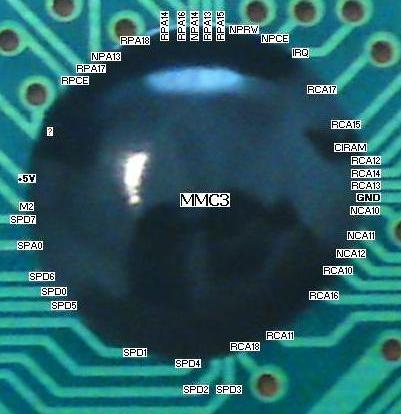
It is better to start from connector.
Ok very good. From now on you have to rely on some other info. You need to find out about special lines. You can also ignore identifying exactly some of lines. For example it is not necessary to find out which line is really CHR A17 because we know that lines from CHR A10~A18 connect directly to AX5202P so you can mark those 9 lines which directly come from CHR and go to AX5202P, in generally A10~A18.
Here is 27Pin of 6264 :
D7
D6
D5
D4
D3
GND
D2
D1
D0
A0
A1
A2
A3
A4
A5
A6
A7
A12
?b1--> +5V
WR
b2--> CE2
A8
A9
A11
RD or OE
A10
?a--> CE1
Here is CHR, I bet it is 27C080 :
?a--> Not for CHR
/A13 or CE
D7
D6
D5
D4
D3
D2
D1
D0
GND
?b-->+5v
A0
A1
A2
A3
A4
A5
A6
A7
A8
A9
?d-->A10
GND
/RD or OE
?c-->A11
?e-->A12
?f-->A13
?g-->A14
?h-->A15
?i-->A16
?j-->A17
?k-->A18
?l-->A19
GND
+5V
Here is PRG, I bet it is 27C080 :
?m-->CE
D7
D6
D5
D4
+5V
D3
D2
D1
D0
GND
A0
A1
A2
A10(wrong)-->A3(correct)
?n-->A13
A12
A11
A4
A5
A6
A7
A8
+5V
A9
?o-->A10
?p-->A14
?q-->A15
?t-->A16
GND --> OE
?u-->A17
?r-->A18
?s-->A19
You messed up a little with left side of PRG.
I am not sure about MMC3, I feel that it is not AX5202P!
Try to find out which pin is PRG A19 and CHR A19. It should be a line which is shared between PRG + CHR + MMC3. If no such a line then MMC3 is not AX5202P.
By the way who dumped this cartridge?! And how?!
He dumped it with modified TapeDump programs I provided. Then I assembled the dumped data into an iNES ROM file.
The mapper chip/glop top is a MMC3 clone with multi-cart functions.
MottZilla wrote:
He dumped it with modified TapeDump programs I provided. Then I assembled the dumped data into an iNES ROM file.
The mapper chip/glop top is a MMC3 clone with multi-cart functions.
What hardware he used? Is your program free?
Last time I could dump my 7 in 1 glop top in this way :
How to Dump
But I killed it!
FARID wrote:
What hardware he used? Is your program free?
check:
http://nesdev.com/bbs/viewtopic.php?t=7978Hardware - only NROM devcart to run the TapeDump software.
FARID wrote:
Here is 27Pin of 6264 :
?b1--> +5V
b2--> CE2
b1 and b2 are connected, how can this be different?

FARID wrote:
Try to find out which pin is PRG A19 and CHR A19. It should be a line which is shared between PRG + CHR + MMC3.
How should I do that? I have no clue which one can be it. Maybe CHR A19 is the "?a" line that you identified as CE1. Because I think the PRG A19 is identified correctly.
Quote:
b1 and b2 are connected, how can this be different?
This is one of those special lines! Now you know that you need to tie VCC (pin28) to CE2 (pin26).
Quote:
Maybe CHR A19 is the "?a" line that you identified as CE1
No I am sure ?a is CE1. Try to compare 6462 glop top with this :

See? They really match each other!
But you are unlucky about MMC3 glop top, it doesn't match anything! So there is no way we can find out what the hell it is! It really has extra address lines and so called registers!
I don't know if it is really possible to control PRGA19 and CHRA19 (and maybe CHRA18?) with the help of some TTL chips.
Another issue is about size of PRG and CHR. They don't match your ROM size at all! I don't have any idea how this is possible on earth! Maybe those Chinese guys shared CHR between two Rockman version!
Well thanks for your help, that's why I wanted to use the TTL logic in the first place. There are countless of pirate mapper globtops with different functions. And you cannot believe that all pirated MMC3 carts use that "AX5202P" you've found in one of them. There even may be more "components" under that glob.
I went on this road many times and never got positive results. But it's fun to play in paintbrush
FARID wrote:
Now you know that you need to tie VCC (pin28) to CE2 (pin26)
Yes, I'm aware of putting logic 1 on chip-enable, thanks. There's nothing special about it, it's active High.
But I don't think you should rely on original chip pinout, those chinese components covered with epoxy can have different pinouts, and the routes that are visible after exiting the glob can already be switched. AND you don't know if there are not any other "miracles" under the epoxy glob.
FARID wrote:
Another issue is about size of PRG and CHR. They don't match your ROM size at all! I don't have any idea how this is possible on earth! Maybe those Chinese guys shared CHR between two Rockman version!
Are you taking into account that the 27C160 is 16-bit? If it's used in 8-bit mode, I don't see any "impossibility" in that...
The PRG-ROM is certainly 16 megabits (equal to a 27C160). And yes ofcourse it's used in 8bit mode. CHR-ROM is 4 megabits, the first 2 megabits are for Rockman 5. The next 1 megabit is Rockman 3. The next 1 megabit (but only the first 8 kilobytes really) is for the Menu Select graphics.
Like I said before, the gloptop that contains the MMC3 clone also contains other mapper functions for the multi-cart capability. This extra capability could be added onto a normal MMC3 with either a CPLD or enough 74 series chips probably. I've already outlined what capability and for what hardware purpose some of the multi cart function is about.
Most of the components are wired up just like a normal MMC3 game. But some extra logic controls things beyond the MMC3 like the higher PRG-ROM lines, CHR-ROM lines, and CHR chip control for CHR-RAM or CHR-ROM enable.
@ jpx72
Please complete the diagram based on my suggestions and make it a one piece picture. Maybe some other one gets interested in it and wants to continue the work. Which software did you use to draw the lines? It is really a great job!
@ MottZilla
If PRG is a 27C160 then where is these pins :
/E
/G
/BYTE VPP
Q8~Q14
Q15A-1
Maybe it doesn't need Q pins which are output, but I don't believe it doesn't need /E, /G and /BYTE VPP then where are they?
If CHR is a 27C040 then it just needs A10~A18 to operate at 512KB but as you can see there is another pin which I guess it is A19, if it is not A19 then what is that pin?!
As you can see :
PRG is missing some pins so it is not 27C160 but 27C080
CHR has more pins than necessary so it is not 27C040 but 27C080
My 6-in-1 Rockman (Unl)[U][!].nes is :
Size : 2,621,516 bytes
MD5 : 7E4A01CC85CEBBD7181DA504DAAC6950
Length : 28004C
Somehow I feel that it is not in correct size :
256 + 128 + 120 + 8 + 256 + 256 + 512 + 512 + 256 + 128 + 8 + 120 = 2560 KB
2560 * 1024 = 2621440 + 16 (Header) = 2621456 bytes -->
Length 280010
Where is my mistake?!

FARID wrote:
@ jpx72
My 6-in-1 Rockman (Unl)[u][!].nes is :
Size : 2,621,516 bytes
MD5 : 7E4A01CC85CEBBD7181DA504DAAC6950
Length : 28004CWhere is my mistake?!
This rom is in UNIF format. You must cut out the UNIF header data, use
ucon64 like this:
rename your rom to rockUNIF.nes and run in command line
ucon64.exe rockUNIF.nes rockINES.nes -inesThat will convert UNIF header to INES. After that:
ucon64.exe rockINES.nes --sYou'll get files:
rockINES.prg - 2048 kB
rockINES.chr - 512 kB
rockINES.prm - you can delete this one
And:
PRG=256+128+120+8+256+256+512+512=2048
CHR=256+128+8+120=512
- check my first post and read it throughout again.
BTW drawing software? WinXP's paintbrush
FARID wrote:
If PRG is a 27C160 then where is these pins :
/E
/G
/BYTE VPP
Q8~Q14
Q15A-1
/E = CE
/G = OE
/BYTE CPP= program supply
-read the "Operating modes" table in datasheet of 27C160, you'll see pins /E and /G in
read mode must be LOW (V-IL) that means connected to ground (GND). /BYTE must he High (V-IH) that means +5V. So these lines are directly "cured" this way, so you don't see them coming out of the glob.
What the data lines concerns, you need to make 8 data lines out of 16. So you need to combine Q0+Q8, Q1+Q9 ...Q7+Q15 to get them. For that a pair of 7402 (NOR gate) can be used (or OR gate, but I don't know the number of IC with 4 ORs and 8 inputs).

So there must be something else under that "PRG" glob to do that.
FARID wrote:
@ jpx72
Please complete the diagram based on my suggestions and make it a one piece picture.
UPLOADED new version, without your guesses (there have been mistakes, double A10 and A13, maybe more), just the comfirmed ones:

It's better to view now, maybe you can review your pinout again.
Here is my guess about the pinout
Most of them should correct. But this thing is really complex than I expect it!
MMC3 has some extra pins :
CHR A18 (CHR + MMC3)
CHR A19 (CHR + MMC3)
CHR /A13 (Connector + CHR + MMC3)
PRG A1 (Connector + PRG + MMC3)
PRG A4 (Connector + PRG + MMC3)
PRG A12 (Connector + PRG + MMC3)
PRG A19 (PRG + MMC3)
PRG OE (PRG + MMC3) (?)
I am not sure about PRG OE, because normally OE of PRG connects to GND. There are 2 GNDs at PRG, there is a chance that one of them is OE and then this pin of MMC3 can have another function.
After all now you know which pins are critical so you need some other TTL to use on these pins.
FARID, the Rockman Pirate doesn't use a 27C160 EPROM, it has a 16 megabit size 8bit MaskROM for PRG-ROM. You could use a 27C160 EPROM if you were to build your own version of this cartridge, just set it to 8bit configuration.
The BYTE signal is related to 27C160's dual 8bit/16bit operation. The MaskROM won't have that. But it will have /CE and /OE signals. It will have D0 to D7 and all appropriate Address Lines and power and ground. Most of the upper address lines from PRG-ROM will go from one gloptop to the other. I think the top 4 lines, A20 to A17, shall all go to additional non-MMC3 logic. A16 to A0 should connect to MMC3 logic or Cartridge Connector normally.
I'm pretty sure 16megabit (2048kiloByte) size 8 bit-only ROM (PROM/EPROM/EEPROM/OTP EPROM) is not manufactured. Not saying those chinese guys cannot do one themselves.
You do not understand. This is not a PROM, EPROM, or any other Programmable ROM. It's a MASK ROM. And yes 16 megabit 8bit Mask ROMs exist. Tons of them are in Super Nintendo Cartridges. And plenty are in Chinese Multi Cart Pirate games as well.
jpx72 wrote:
What the data lines concerns, you need to make 8 data lines out of 16. So you need to combine Q0+Q8, Q1+Q9 ...Q7+Q15 to get them. For that a pair of 7402 (NOR gate) can be used (or OR gate, but I don't know the number of IC with 4 ORs and 8 inputs).
If you closely examine the OR/NOR function you'll find that this doesn't make any sense. There is a very basic component for the function you're looking for (logically selecting between two inputs) called a multiplexer ("MUX").
Yes, a multiplexer can be used too, maybe even better than adding those together with an OR (a+b). Thanks for the tip.
Well let's forget about the 2048 8-bit ROM.
Anybody here knows how to adress
- lines A19 and A20 of the PRG
- line A18 of the CHR
to a "normal" MMC3 board like TKROM? Some diagram with 74xx chips or something similar?
I'm playing around with this ROM and the first one I tested (Rockman) has serious slow down issues while scrolling the screen ... (Is that related to the MMC3 IRQ timer ?)
It gave me a BAD first impression on these mapper conversions ...
P.S.: I was testing it on the real hardware: NTSC US NES + Nintendo TSROM board with CHRAM (make it wprk like TGROM) mod.
Anyone with the original pirate cart can confirm if Rockman 1 has slowdowns ? If that is not the case, it could be that the menu program explicitly disables the IRQ timer on the mapper chip.
Yes, the menu program disables the IRQs. I don't think Rockman 1 or 2 disables the IRQs themselves.
The gameplay of Rockman 1 is ok on the original cartridge, the scrolling of screens in all directions is smooth.
Since I don't have original Rockman 1 at hand and I don't remember if the slowdown in case of many enemies on screen should be so visible, if not, it may be an issue of this multicart.
Kind of strange for there to be slowdown, it's not like there's a lot to adapt with UNROM.
Quote:
Yes, a multiplexer can be used too, maybe even better than adding those together with an OR (a+b). Thanks for the tip.
Definitely better because ORing two data lines will yield nonsense data. Plus OR gate chips don't have 3-state buffers required for interfacing to a data bus.
--
If I really wanted to make a new cart of this I'd sooner hack the menu to work with simpler hardware, or write another one. Hacking the mapper could get it down to 3 or 4 extra chips instead of the large amount with the current inefficient design.
The decoding isn't very hard because you can take advantage of a pattern:
Code:
rockman size
1 2m/cram -- pad prg and use for menu
2 2m/cram
4 4m/cram
6 4m/cram
3 2m/2m -- pad chr
5 2m/2m
- 4m/2m -- unused, undecoded
- 4m/2m -- unused, undecoded
So technically you could decode a '161 using the MMC3's WRAM decoder, then use another couple chips to fix the addressing.
PRG bank order in ROM:
$000000: MM1 and menu
$040000: MM2
$080000: MM3
$0C0000: MM5
$100000: MM4
$180000: MM6
Values written to 161:
Code:
3210 $6000-$7FFF: PRG ROM bankswitch
||||
|||+- Select half of 512 KiB bank (ignored when bank size is 512 KiB)
|++-- Select 512 KiB bank
|+--- Set PRG ROM bank size (0: 256 KiB; 1: 512 KiB)
+---- Select CHR chip (0: CHR RAM; 1: CHR ROM)
$0: MM1 and menu
$1: MM2
$A: MM3
$B: MM5
$4: MM4
$6: MM6
PRG A20-A19: 161 D2-D1
PRG A18: MMC3 A18 if 161 D2 is true else 161 D0
PRG A17-A0: From MMC3
CHR A18: From 161 D0
CHR chip enables: Decoded from 161 D3
In addition to the 161, I see an inverter to decode the CHR ROM enable (unless your CHR ROM has a positive enable), a multiplexer to generate PRG A18, and some sort of power-on-reset circuit to force 0 into the 161 on boot.
So I burnt a copy of the original Rockman ROM into an UNROM board and tested.
While it also suffer of some slowdown (it's the original game, not an patched ROM) it's not even close to the slowdowns I had with the MMC3 patched Rockman rom.
If anyone feels like testing, play the 1st part of Iceman stage and try to put many enemies on the screen.
MMC3 also requires four writes to change a 16 KiB PRG bank, while UNROM requires one.
Code:
unromsetbank: ; as might have been used in Mega Man
tay
sta busconflict,y
; 6 cycles so far
rts
busconflict:
.byt 0, 1, 2, 3, 4, 5, 6, 7
mmc1setbank: ; as might have been used in Mega Man 2
sta $E000
lsr a
sta $E000
lsr a
sta $E000
lda #0
sta $E000
sta $E000
; 26 cycles so far
rts
mmc3setbank: ; as might have been used in Mega Man 3-6
asl a
ldy #6 ; Reg 6: PRG bank $8000
sty $8000
sta $8001
iny ; Reg 7: PRG bank $A000
sty $8000
ora #$01
sta $8001
; 24 cycles so far
rts
With a lot of bankswitches, this 18-cycle difference might be the last straw that causes the main loop to exceed 241 lines. If the original bankswitch was inlined and the ROM hack patches each mapper write with a JSR/RTS pair (likely), the difference might be 30 to 32 cycles. How many times does Mega Man 1 bankswitch per frame?
You may well be right tepples, I've noticed some discrete logic games that have a simple write register experience slowdown with more complex slower to write mapper registers which probably is because they bankswitch alot as it didn't normally take so much time to do so.
If the IRQs were firing I think you'd experience something worse but I'm not sure. Or maybe they bothered to alter the IRQ routines to disable it if they did fire. I didn't study the hacked versions much.
But to be fair to the MMC3: A program originally designed for MMC3 might use $A000 as the only switchable bank and leave bank select set to $46 (or $C6 to swap the pattern tables) most of the time. This leaves one instruction to switch $A000 (that is, STA $8001) throughout the main thread, which is fast as UNROM. The only time the mode would change would be to load a new DMC sample into $C000 ($8000:=$47, $8001:=bank number, $8000:=$46) or to change CHR banks (in the NMI or IRQ handler, after which point back to $46). It's just using MMC3 to emulate UNROM that might run into slowdown.
jpx72 wrote:
Yes, a multiplexer can be used too, maybe even better than adding those together with an OR (a+b). Thanks for the tip.
There is already one built-in 27xx160 and controlled by pin BYTE/WORD.
Reverse menu first.
l_oliveira wrote:
If anyone feels like testing, play the 1st part of Iceman stage and try to put many enemies on the screen.
jpx72 wrote:
Since I don't have original Rockman 1 at hand and I don't remember if the slowdown in case of many enemies on screen should be so visible, if not, it may be an issue of this multicart.
Just wanted to add a piece of informations someone may find useful (or not).
Since I have two (2) different carts of that Rockman 6in1 I tried to find out if there are any differences, but just before that I'd like to personally say I think all of them Rockmans suffers some kind of slowdowns when there is like too many things on the screen at the particular time (i.e. just try to "collect" as many bees as you can right at the beginning of the "Hardman" stage in Rockman 3, you'll notice that right away), so it's kinda "natural" I'd say, as for that "Iceman" stage from Rockman 1 I haven't noticed anything unusual, maybe just a little slowdown
l_oliveira, but there is this one enemy on some other stage in Rockman 1 (I don't exactly remember where it was...), flying rocket or something, when you hit it, it explodes with massive blast radius causing a huuuuuge slowdown, that is something, or hell even while firing "electro shot" you can experience something little bit similar.
Now, on to the differences. Right of the bat not only the casing is different but also a PCB and a menu screen :
"Regular" Rockman 6in1 cart >>
http://img535.imageshack.us/img535/3084/r6in1.jpg
and it's PCB (hi-res) >>
http://img812.imageshack.us/img812/3319/r6in1b.jpg
"Other Rockman 6in1 cart >>
http://mwk.netne.net/006.jpg
it's PCB (hi-res) >>
http://img233.imageshack.us/img233/4350/r6in1a.jpg
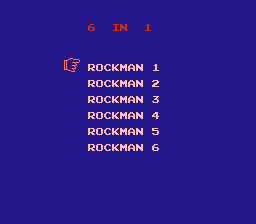
and game select screen >>
http://img825.imageshack.us/img825/1850/r6in1scr.jpg
What's also kinda weird is this "Loading..." screen that appears for like noticeable half a second right after choosing any game. It's like all the games are packed or something and they're need to be decrunched, I dunno, but I always enjoy watching that flashy quickie load screen
I believe that Sony chip from the back side is just a regular SRAM, but the "main" one is that "MX29L3211MC-10 - 32M-BIT [4M x 8/2M x 16] CMOS SINGLE VOLTAGE PAGEMODE FLASH EEPROM - Macronix International" >>
pdf here, so that glob-top seems to be only just a mapper (with/without menu screen), correct me if I'm wrong.
As for the games, all Rockmans aren't "screwed up" with extra lifes, only copyrights have been removed from Rockman 3, the rest is fine... but, yeah, one big thing that affects the entire, sweet cake that multicart is... unfortunately at precise point of Rockman 1 (that waterpipe at the beginning of the 3-rd (I believe?) part of Dr.Wily's stage, right after water flushes in) game suddenly (!) switch back to the title screen like nothing ever happen

Believe me, I've tried everything on like 4 or 5 different consoles (including famiclones).
Sad sad thing it is.
Anyway, I hope all this will help somehow.
The second Rockman 6-in-1 PCB looks like it stores CHR data inside the large flash chip and loads it into the same large SRAM chip it would use for any of the games. That is certainly one way to do it, but then you need a bigger PRG-ROM and a 256KByte SRAM.
Rockman resetting could be for many reasons. Maybe they just did a poor job of hacking.
2 MWK What's the part number of "back side" IC? Also love the PCB(not mapper LOL) with place for second flash chip
2 MottZilla hi, boss

SONY CXK582000M.
256KB 8-bit low power Static RAM .
The 4MB SOP FLASHROM (the Macronix chip) is 3.3v so the Chinese is cheating with a diode to drop the voltage a bit. Don't play that cart much as it will eventually blow itself or your nes (or both).
l_oliveira wrote:
The 4MB SOP FLASHROM (the Macronix chip) is 3.3v so the Chinese is cheating with a diode to drop the voltage a bit. Don't play that cart much as it will eventually blow itself or your nes (or both).
It must blow asap, otherwise Mao's kids will starving

If someone can convert Rockman 3 and 5 from TLROM to TGROM, I can design a new hardware for this cartridge by using :
1 * M27C322 --> PRG
1 * 6264 --> SRAM
1 * AX5202P --> MMC3
1 * 74HC174 --> PRG Latch
2 * 74HC157 --> Data line separator
1) Adapting CHR ROM games to CHR RAM is not easy, and it will result in even MORE slowdown, now with graphical glitches if the game bankswitches for animation
2) You must mean a 74'257, because a '157 does not have 3-state drivers for interfacing to a data bus.
FARID wrote:
If someone can convert Rockman 3 and 5 from TLROM to TGROM
It's usually not possible to convert games with CHR-ROM to CHR-RAM. With CHR-ROM, the MMC3 can switch large amounts of tiles every frame, because all it takes is a few mapper writes.
With CHR-RAM however, all tiles must be manually updated during VBlank, byte by byte, which severely limits the amount of tiles that can be updated each frame (considering the other tasks that must be performed during VBlank, you'll realistically manage to update between 4 and 8 tiles each frame, while with CHR-ROM you can even change the whole 512, several times over, if you wish to).
Notice how Mega Man games that use CHR-RAM have much less background animations that aren't palette-based (because palette animations are cheap to do no matter what kind of CHR you use) than CHR-ROM ones.
Well, the point is that the game has 256KB of video memory so it's writing the whole CHR ROM in RAM then using it as ROM afterwards ...
That way it works just fine... Only annoyance is the "loading" screen you get when it's copying the tiles to CHR RAM.
l_oliveira wrote:
Well, the point is that the game has 256KB of video memory so it's writing the whole CHR ROM in RAM then using it as ROM afterwards ...
Sure, in that case RAM works just fine. But FARID asked for a TLROM to TGROM (which has only 8KB of CHR-RAM) conversion, which is not possible. 256KB RAM chips (with the packaging and voltage used by NES carts) are very hard to find compared to 32KB and below, though.
tokumaru wrote:
l_oliveira wrote:
Well, the point is that the game has 256KB of video memory so it's writing the whole CHR ROM in RAM then using it as ROM afterwards ...
Sure, in that case RAM works just fine. But FARID asked for a TLROM to TGROM (which has only 8KB of CHR-RAM) conversion, which is not possible.
I've fit ram chips on several boards and I even have a modded TLROM board with W-RAM, chr-ram and a option to run with 4 screen mirroring which is enabled by just toggling a bit. Any configuration is possible if you know how to do it.
The trickiest part was create the extra copper tab on the board edge connector to get the PPU /WE pin... This board can play any MMC3 (or namco games that are similar to MMC3).
Possible it is ... Worth your while ? I don't know ... I did it anyway lol


Plays Gauntlet great, btw.
2M isn't a standard RAM size (2M basically means two 1M arrays in a package) so I have no idea where they got those chips and there's no way I'd make anything, even a one-off, with a rare part. It's not even economical to when 64K RAM and EPROM are so cheap. Basically you're trading board space for part cost, but in a small run when you don't have a massive supply of nearly free pulls like the bootleggers must have, go with part cost. Also 2M of RAM is a very capable part completely put to waste in a multicart.
Nevermind the 2M RAM, using a 27C322 isn't smart since:
- it's 16-bit only so it requires external byte selection
- basically 14 of the 32 megabits will be wasted
- '322 are less common, more expensive and more in demand than '160 or '080 and can be put to vastly better use in other applications
- it wastes power since you'll have to keep the ROM enabled and outputting, use pullups on the multiplexer inputs or use 74LS257 instead of a CMOS part
Also the '174 is a good part due to availability, but:
- the '161 is more common and cheaper in DIP packages, the opposite is true for SOIC however
- it will require an additional decoder unless you use the address bus for input, the '161 has a decoder for "free" (the /load input)
- 6 bits are not necessary for this task, only 3 are. If you were to use a standard parallel register instead of the '161 the sensible one to use would be the '175 which has complementary outputs which is good for decoding
The logical solution for this this multicart's redesign is to use a 16M PRG EPROM (which is still slightly wasteful) or better yet two 8M, and a 4M CHR EPROM with 64K CHR SRAM.
Quote:
1) Adapting CHR ROM games to CHR RAM is not easy, and it will result in even MORE slowdown, now with graphical glitches if the game bankswitches for animation
Megaman 4, 6 are TGROM, so I think it is possible to convert 3, 5 to TGROM too. Maybe this conversion is hard but it is the only way to redesign a simple hardware.
Quote:
2) You must mean a 74'257, because a '157 does not have 3-state drivers for interfacing to a data bus.
I will use a tool to put 3 PRG into odd offsets (PRGo) and 3 other PRG into even offsets (PRGe) and then use two 157 to separate 16bit data line to even and odd 8bit data line :
M27C322 --> PRGo PRGe PRGo PRGe ....
D0~D7 --> PRGo
D8~D15 --> PRGe
174 latches the signal generated by game selection menu to run a desired game. I have this special menu from my Kunio 8 in 1 and I can use it to make this cartridge but all games must be TGROM!

FARID wrote:
Maybe this conversion is hard but it is the only way to redesign a simple hardware.
No it is not, if you reread this thread you'll see it discussed.
Quote:
I will use a tool to put 3 PRG into odd offsets (PRGo) and 3 other PRG into even offsets (PRGe) and then use two 157 to separate 16bit data line to even and odd 8bit data line :
M27C322 --> PRGo PRGe PRGo PRGe ....
D0~D7 --> PRGo
D8~D15 --> PRGe
You don't get it, it won't work. If you want to waste your time, money and possibly damage your hardware go ahead, but I'm telling you a '157 is unsuitable. Please read more about digital logic and computer buses before building your circuits. Funny that this is the second misinformation about interfacing with the data bus in this very thread.
Quote:
174 latches the signal generated by game selection menu to run a desired game. I have this special menu from my Kunio 8 in 1 and I can use it to make this cartridge but all games must be TGROM!
I understand, but just because your other game uses a '174 doesn't mean you have to use it. I was suggesting that another chip would be more suitable.
Kunio games are completely different than Rockman games, if I remember correctly they are all a uniform size--1M/1M. Because of this there is more to it than adding a selection register, you must FIX the mapping with extra logic which you make no mention of. You also don't make any mention of decoding the register; as I suggested earlier the "free" way is through the MMC3's WRAM decoder, but it's possible you may have to hack around any sort of copy protection which accesses $6000-7FFF.
There is very little reason to reuse your Kunio menu as it will need an overhaul no matter what.
Quote:
FARID wrote:
If someone can convert Rockman 3 and 5 from TLROM to TGROM
What for?
Quote:
2) You must mean a 74'257, because a '157 does not have 3-state drivers for interfacing to a data bus.
No, it's for control some address lines of CHR(PRG)ROM. '157 is ok for that, but better to use another IC.
Actually i almost finished schematics for this mapper according to
MotZilla's description. Just want to minimize amount of IC's.
Feel free to ask questions
80sFREAK wrote:
Quote:
FARID wrote:
If someone can convert Rockman 3 and 5 from TLROM to TGROM
What for?
To omit at least CHR-ROM.
Quote:
Feel free to ask questions
How many ICs do you use?
80sFREAK wrote:
No, it's for control some address lines of CHR(PRG)ROM. '157 is ok for that, but better to use another IC.
"2 * 74HC157 --> Data line separator"
"and then use two 157 to separate 16bit data line to even and odd 8bit data line"
And actually if it were to control address lines (UNROM) '157 would be appropriate since it's more common than OR gates.
kyuusaku wrote:
80sFREAK wrote:
No, it's for control some address lines of CHR(PRG)ROM. '157 is ok for that, but better to use another IC.
"2 * 74HC157 --> Data line separator"
"and then use two 157 to separate 16bit data line to even and odd 8bit data line"
And actually if it were to control address lines (UNROM) '157 would be appropriate since it's more common than OR gates.
Why do you think it is not possible? I know this method isn't common but it doesn't mean it is not possible at all. I will test it for sure, whenever I get some free time.
FARID wrote:
80sFREAK wrote:
Quote:
FARID wrote:
If someone can convert Rockman 3 and 5 from TLROM to TGROM
What for?
To omit at least CHR-ROM.
You don't need it.
FARID wrote:
How many ICs do you use?
8 at moment. It's a lot, i would like to cut amount, but i don't think it's possible without patching menu. If patch the menu - 1 less.
This glob-top mapper can contain some other functions for other multicarts, but only decapping can proove it.
2 kyuusaku, right, that's made me double facepalm.
FARID wrote:
Why do you think it is not possible? I know this method isn't common but it doesn't mean it is not possible at all. I will test it for sure, whenever I get some free time.
Why do you need 16bit data?

kyuusaku wrote:
And actually if it were to control address lines (UNROM) '157 would be appropriate since it's more common than OR gates.
Thanks. Added to
the wiki page. More ways to implement the same function are always appreciated.
you can build stand-alone OR gate from 2 diodes and 1 resistor.
Well, back to the topic, schematics complete and pre-checked. Now have to build prototype

Quote:
You don't need it.
Rockman 3, 5 need CHR-ROM, have you found TGROM version of them?
Quote:
Why do you need 16bit data?
If all games are TGROM and uniform, then it will be 6*512KB=3072 for PRG, this much of PRG needs 3*27C080 or 1*27C322
After separating Rockman 4, 6 from Chinese 6 in 1 ROM, they won't work with their original header from Japanese ROM. They must be TGROM but why won't work under that header?! Others work fine.
FARID wrote:
Quote:
You don't need it.
Rockman 3, 5 need CHR-ROM, have you found TGROM version of them?
Doesn't exist. There is a reason the games use CHR-ROM and not CHR-RAM. This pirate multi already exists. Why try to re-engineer it? Really just slap enough AND/OR gates together and you can make whatever multi-cart logic you want. And in that case you could just grab a CPLD or maybe a PAL to handle it.
MottZilla wrote:
This pirate multi already exists. Why try to re-engineer it? Really just slap enough AND/OR gates together and you can make whatever multi-cart logic you want. And in that case you could just grab a CPLD or maybe a PAL to handle it.
AMEN! Apparently isn't not just me.
If you'll accept crap conversions of the original game just buy the multicart or play in an emu.
If you want the original quality buy the readily available original carts. Yes they aren't cheap for all 6 of them but they are great games worth the expense.
If you really want all of them in a single cart to make as some sort of project: Do it right and put all the games on a single cart with their original mapper/board layout mashed into one. Either implement a ton of switches and logic or pick up a CPLD and teach yourself a thing or two. All of these games could be put on one cart with the original mappers. I don't see why it's worth the effort but it sounds like some people might based on the thread.
But don't let me tell you what to do...
FARID wrote:
Quote:
You don't need it.
Rockman 3, 5 need CHR-ROM, have you found TGROM version of them?
Again, you don't need it.
FARID wrote:
If all games are TGROM and uniform, then it will be 6*512KB=3072 for PRG, this much of PRG needs 3*27C080 or 1*27C322
Nope. 512kB for CHR and 2MB for PRG. That's all you need.
2 MotZilla hi, boss
MotZilla wrote:
Really just slap enough AND/OR gates together and you can make whatever multi-cart logic you want.
Most likely yes, but i had to fall back from your description to the first table. By the way, can you confirm that data exactly correct?
MotZilla wrote:
And in that case you could just grab a CPLD or maybe a PAL to handle it.
Oh, c'mon! Only discrete are true

It's ended with 8 common IC's
2 infiniteneslives I took this mapper as a small challenge. And i will build only mapper, not really interested in Rockman games.
I suggest this design, it needs 6 ICs :

A bit more than 6(plus you need much bigger EEPROMs), but you gave me good idea, how to return to main menu without powering off console. Thanks for that.
Again, just checked my drawings with "fresh eye". 8 common IC's can do the job. Patching menu can save 1 IC and using different decoder/latches can save another one
FARID wrote:
I suggest this design
No offense, but you're really missing the point about the issue with the '157 not being tristate outputs. Assuming you've got those tied to the NES data bus (and not some separate crazy MMC3 data bus per the label) they will NEVER work. Those chips will ALWAYS drive the data bus lines to a logic 1 or 0. and the CPU MUST be able to drive those lines when it's writing to it's various locations. Your cartridge can ONLY control the data bus when the NES is reading from the ROMs (PRG /CE low and PRG R/W high). You are obviously violating this fundamental rule of bidirectional data buses.
infiniteneslives wrote:
FARID wrote:
I suggest this design
No offense, but you're really missing the point about the issue with the '157 not being tristate outputs. Assuming you've got those tied to the NES data bus (and not some separate crazy MMC3 data bus per the label) they will NEVER work. Those chips will ALWAYS drive the data bus lines to a logic 1 or 0. and the CPU MUST be able to drive those lines when it's writing to it's various locations. Your cartridge can ONLY control the data bus when the NES is reading from the ROMs (PRG /CE low and PRG R/W high). You are obviously violating this fundamental rule of bidirectional data buses.
I told him that, even posted about it here ...
He said it works. Fine with me.
I know I won't be doing that on my Famicom, though...
Well, maybe there is '245 or '541 involved
80sFREAK wrote:
Well, maybe there is '245 or '541 involved
I'm sure there isn't ... I talk to him through MSN and he mentioned he intend to use this configuration. I told him it will not even boot.
Oh well, let it go. Still wonder, why 16-bit bus?
80sFREAK wrote:
Oh well, let it go. Still wonder, why 16-bit bus?
He want to salvage chips.
But almost any modern 16-bit flash have Byte/Word config pin
80sFREAK wrote:
But almost any modern 16-bit flash have Byte/Word config pin
It's the case of salvaging whatever you have in hand, I'm quite used to that and a lot of times people ask "why you used this part, that other one would have been so much better ... " yes, but these people don't realize that you can make the exact same digital circuit from a hundred of different ways and all can do the exact same thing. It just depends on which parts are easier to get.
That's what kyuusaku is talking about when he said " '157 would be appropriate since it's more common than OR gates."
Back then Nintendo would be buying new parts so an 74LS32 would cost less than a 74LS157 in bulk quantities hence their design choice.
At this point we're mostly recycling old technology out of passion so the considerations to be made are slightly different. Don't you think so ?
80sFREAK wrote:
MotZilla wrote:
Really just slap enough AND/OR gates together and you can make whatever multi-cart logic you want.
Most likely yes, but i had to fall back from your description to the first table. By the way, can you confirm that data exactly correct?
The table I posted way back in this thread should be correct. The Rockman multi was dumped and emulated with the information. The table for register settings can be found in the menu rom.
In my opinion if you are going to make a multi cart for the Rockman games you should not take the easy way out and end up with a product that is cheap or poor quality. It would be appealing to have all the games on one cartridge, just like Super Mario All Stars, Mega Man The Wily Wars, or Ninja Gaiden Trilogy. But not if the games function poorly.The first two games being the obvious problem using different mappers.
At moment i'm after built hardware master(menu) mapper. As you confirmed table, logic should be correct, but i want to see LED's blinking
You sounds, like i should release this on commercial basis. Should i?
Donations are welcome
I'm not sure what you mean. Did you construct a PCB that you wire to a MMC3 board or something?
How about this new logic :
27C080 --> PRG1
27C080 --> PRG2
27C040 --> CHR
6264 --> SRAM
AX5202P --> MMC3
74HC174 --> Latch
74HC174 Input/Output :
PRG D0 --> PRG1 A19 + PRG2 A19
PRG D1 --> PRG1 A18 + CHR A18
PRG D2 --> PRG1 /OE
PRG D3 --> PRG2 /OE
PRG D4 --> CHR /OE
PRG D5 --> SRAM /OE
Rockman 5 --> 256 + 256 --> PRG1 + CHR --> XX101000 --> 28 --> menu
Rockman 3 --> 256 + 256 --> PRG1 + CHR --> XX101010 --> 2A
Rockman 1 --> 256 + 8 ----> PRG1 + SRAM -> XX011001 --> 19
Rockman 2 --> 256 + 8 ----> PRG1 + SRAM -> XX011011 --> 1B
Rockman 4 --> 512 + 8 ----> PRG2 + SRAM -> XX0101X0 --> 14
Rockman 6 --> 512 + 8 ----> PRG2 + SRAM -> XX0101X1 --> 15
MottZilla wrote:
I'm not sure what you mean. Did you construct a PCB that you wire to a MMC3 board or something?
Yes, it's a master(menu) mapper for MMC3 boards. Prototype phase at moment. 8 common IC's final amount. No more, no less.
2 FARID And where is menu code?
Plus you wasting quarter of CHR chip.
Using the scheme I suggested I got it into a generic 3-bit register, a '157/257 and a lone OR gate.. which kinda sucks. The OR gate can be implemented with diodes, meh, or a '139 which would give the register more selective decoding.
kyuusaku wrote:
Using the scheme I suggested I got it into a generic 3-bit register, a '157/257 and a lone OR gate.. which kinda sucks. The OR gate can be implemented with a '139 which would give the register more selective decoding.
Instaed of OR gate use diodes, Luke
You are on the way, but far behind
I had thought of that but diode gates are horrible. Far behind from what? I could implement this in about 10 minutes on a CPLD board, I have no interest apart from optimizing logic.
kyuusaku wrote:
I had thought of that but diode gates are horrible. Far behind from what? I could implement this in about 10 minutes on a CPLD board, I have no interest apart from optimizing logic.
How about discrete logic?
P.S. Not you, software you using actually
P.P.S. Sorry, dude, but people, who making everything on CPLD or Atmega converted electronics from art, which suppose to be, into the fastfood.
What do you mean? Am I in some kind of competition? What will I win? lol
The original mapper is around 10 chips. What's the point of reimplementing that when it can be done better? With 6-8 chips the actual UOROM logic can be integrated so there isn't any slowdown. If I were to build something so obnoxious I'd rather go for a 15 chip MMC1 design, or 11 chip (IIRC) FME7.
Edit: It's nice to see passionate people, but I don't think you know how ridiculous your comment is. The truth of the matter is that discrete electronics are poor performers and circuit design and layout is often better optimized according to physics, not an individual's take on aesthetics. Maybe sometime you'll come around to believing that IP can be artistic. I might agree that IP implementations are rarely beautiful but rather the ideas are beautiful. I'm not sure if you're convicting LSI in general, but I think IC design is probably the highest form art in electronics, especially fully-custom designs.
CPLDs are more efficient. Saves board space too. Ofcourse discrete logic is friendlier to those unable to take advantage of CPLDs.
Competition? No, no way. It's about art, but you are too money/prize oriented. Want to join?
Art or fastfood. You choose. I understand advantages of CPLD if you doing commercial(say fastfood) project. My goal is make true vintage style device - how often CPLD's used back in time? So this is the answer, otherwise i would go just quietly reproduce this cart and sell "ready to eat" product
Sorry, i have to go. See you later. Don't flood the thread
80sFREAK wrote:
P.P.S. Sorry, dude, but people, who making everything on CPLD or Atmega converted electronics from art, which suppose to be, into the fastfood.
I want to argue so badly... But I know it's not worth the time or effort. My time is better spent designing 'fast food'
So ehrm yeah, new proposed parts list:
- MMC3
- '161
- '161
- '257
- '257
- '02
- 4 pullups
- RC POR
--- - 27C080
- 27C080
- 27C040
- 62C64
Features:
- only 8-bit ROMs
- under 2M of 20M wasted
- integrated UOROM for slowdown-free Rockman 1 and 2
In authentic bootlegger style if I were to build this I'd opt for 2x PAL16L8 instead of the 74 series & pullups.
Oh, boy... I am so disappointed... Why do you trying to change specs? Can not copy simple chinese mapper?
??? What is your problem? lol
Implementing this Chinese mapper is your project right? What does that have to do with me? I've already stated 3+ times why I wouldn't implement that logic. Low English comprehension? Age deficient syndrome? Another sick technical troll? You know you can ask for help instead of trying to coerce it out of people.
kyuusaku wrote:
I could implement this in about 10 minutes on a CPLD board
Don't sanctions make it kind of hard for FARID to get CPLDs?
And what's "Age deficient syndrome"? Google doesn't appear to show anything relevant.
kyuusaku wrote:
??? What is your problem? lol
Implementing this Chinese mapper is your project right? What does that have to do with me? I've already stated 3+ times why I wouldn't implement that logic. Low English comprehension? Age deficient syndrome? Another sick technical troll? You know you can ask for help instead of trying to coerce it out of people.
Sounds very racist.
Nothing to say
@
Change talk to personality
2 tepples don't think about sanctions, maybe he just loves DIP IC's
kyuusaku wrote:
integrated UOROM for slowdown-free Rockman 1 and 2
I'm not sure if Rockman 2 could be hacked to UOROM or not. It normally uses MMC1. I think the only feature it could use that might be an issue is Name Table Mirroring Control.
MottZilla wrote:
I think the only feature it could use that might be an issue is Name Table Mirroring Control.
That's actually pretty easy to add to the upper bits of UxROM by doing the same thing as holy diver to get swapable between H/V. I don't know what mirroring it uses but if it's NT0/NT1 then it's even easier you just use and upper bit of the latch to drive CIRAM A10 directly. (EDIT: although that wouldn't support MM1... and this would also require MM1 to be hacked to support the swapable mirroring that was installed. It shouldn't affect speed or anything though.)
tepples wrote:
Don't sanctions make it kind of hard for FARID to get CPLDs?
I don't have a clue.
Quote:
And what's "Age deficient syndrome"? Google doesn't appear to show anything relevant.
*Deficiency. Maybe it should be "adulthood deficit disorder". Being a teenager I guess.
80sFREAK wrote:
Sounds very racist.
Huh, really? Is it because I don't want to use the inefficient original mapper that happens to be Chinese, because I designated it by its country of origin, or because I brought up English comprehension thus making me "racist" towards you (despite not knowing anything about you)?
MottZilla wrote:
I'm not sure if Rockman 2 could be hacked to UOROM or not.
It can be very easily and the hack is already prevalent. The MMC3 provides the mirroring control..
Hacking an UNROM game to MMC3 might cause problems because MMC3 bankswitch code is slower, but since the MMC1 has the slowest bankswitching method I'm aware of, a conversion from that to MMC3 shouldn't cause any problems.
Farid doesn't care about sanction, if he need it he will probably be done building his own CPLD on breadboard by the end of the month lol
This thread is becoming extremely quotable I must say! Now go back to building art for fast food everyone!
SkinnyV wrote:
Farid doesn't care about sanction
What is "sanction"? It has a lot of meaning in my dictionary.
And here is a new menu with new logic for Rockman 6 in 1. I extracted this menu from 1997 SUPER HIK 8 IN 1 EW-800 :
 Here is the IPS patch if you want to try it
If It works it can fit inside of a FC cartridge but it will be ugly! So I have to test it only on breadboard!
Oh and by the way :
jayminer on nesdev IRC channel helped me to fix the palette and background color of the menu, He is a GOD for sure! Thank you jayminer
A sanction is basically a law that prevents goods from being sold to a specific country. No offense to you Farid, but the U.S. government doesn't exactly agree with the Iranian government. So in order to 'punish' your country/government our government forbids any of our goods to be sold to anyone in your country.
Basically it's illegal to sell American produced goods/semiconductors to Iran, which may prevent you from buying certain things like CPLDs.
Quote:
Basically it's illegal to sell American produced goods/semiconductors to Iran, which may prevent you from buying certain things like CPLDs.
You made my day
I don't remember anything american made, except seeds in the home center and junk arcade boards from scrapyard, which i took only for Motorola MC68000 CPU's. These days 99% electronics MADE IN CHINA
Do you think they care about sanctions?
2 FARID Please check PM inbox
I'm glad my explanation of the word sanction could bring you such great enjoyment.
All I can say is you're really good at making Mark Twain's advice on arguing difficult to follow...
What do you think about this one :

Can I simply share Data lines between PRG1 and PRG2? What about CHR and SRAM Data lines? I want to disable one of them by using /OE. Which one is better to use for disabling the chip : /OE or /CE or even both of them at the same time?
FARID wrote:
Can I simply share Data lines between PRG1 and PRG2?
As long as both aren't selected at the same time, two PRG ROMs can share all CPU address and data lines. This is how the three PRG ROMs in Action 52 are wired up.
Quote:
What about CHR and SRAM Data lines?
As long as both aren't selected at the same time, a CHR ROM and CHR RAM can share all PPU address and data lines. This is how TQROM games (Pinbot and High Speed) are wired up.
Quote:
I want to disable one of them by using /OE. Which one is better to use for disabling the chip : /OE or /CE or even both of them at the same time?
A chip disabled with /CE high runs in a low-power mode; it takes a while after /CE is pulled low before the chip starts producing data. A chip enabled with /CE low but disabled with /OE high draws nearly full power but can deliver data as soon as /OE goes low.
FARID wrote:
What do you think about this one :
Can I simply share Data lines between PRG1 and PRG2? What about CHR and SRAM Data lines? I want to disable one of them by using /OE. Which one is better to use for disabling the chip : /OE or /CE or even both of them at the same time?
couple notes
1) wasting lots of space in ROMs
2) no need two data lines for CHR RAM/CE CHR ROM /CE(use Q and /Q of '175 - once at the time you using CHR RAM or CHR ROM)
3) no need two data lines for PRG1 /CE PRG2 /CE(same as above, only about PRG1 and PRG2)
4) '174('175 as well) latching data on rising edge
That's what i can see from pic above
1) It's not wasting lots of space in ROM, all the Rockman ROMs add up to 18M, unless you can find 3M ROMs you can't come up with 15M PRG and 3M CHR...
2 & 3) Data lines? Neither your correction nor his circuit makes any sense. A register alone can't decode the ROM. Hint: /CE = (/selection + PPU_A13)
4) This actually will work.
Quote:
wasting lots of space in ROMs
It is because I have to make the games a little uniform. Anyway I can't use any smaller IC than 2*27C080 + 1*27C040, do you have any plan to use smaller IC?
Quote:
no need two data lines for CHR RAM/CE CHR ROM /CE(use Q and /Q of '175 - once at the time you using CHR RAM or CHR ROM)
Excellent suggestion, thank you.
Quote:
A register alone can't decode the ROM. Hint: /CE = (/selection + PPU_A13)
Do you mean I can't disable a ROM by using /OE? Considering tepples explanation I feel that using /OE is enough for this case :
Quote:
A chip disabled with /CE high runs in a low-power mode; it takes a while after /CE is pulled low before the chip starts producing data. A chip enabled with /CE low but disabled with /OE high draws nearly full power but can deliver data as soon as /OE goes low.
New :

Rockman 5 --> 256 + 256 --> PRG1 + CHR --> XXXX 0000 --> 00 --> Include Menu
Rockman 3 --> 256 + 256 --> PRG1 + CHR --> XXXX 0010 --> 02
Rockman 1 --> 256 + 8 ----> PRG1 + SRAM -> XXXX 1001 --> 09
Rockman 2 --> 256 + 8 ----> PRG1 + SRAM -> XXXX 1011 --> 0B
Rockman 4 --> 512 + 8 ----> PRG2 + SRAM -> XXXX 11X0 --> 0C
Rockman 6 --> 512 + 8 ----> PRG2 + SRAM -> XXXX 11X1 --> 0D
kyuusaku wrote:
1) It's not wasting lots of space in ROM, all the Rockman ROMs add up to 18M, unless you can find 3M ROMs you can't come up with 15M PRG and 3M CHR...
2 & 3) Data lines? Neither your correction nor his circuit makes any sense. A register alone can't decode the ROM. Hint: /CE = (/selection + PPU_A13)
4) This actually will work.
2 and 3 you can call it "control lines" or whatever, but they transferring data
and i told about using '175 instead of '174
P.S. i am in the good mood
I mentioned '175 on page 4. It doesn't make a good choice though because '175 is not a common part, it's not in production anymore, and how it's being used doesn't make any sense. None of the circuit makes any sense so I joined in.
kyuusaku wrote:
I mentioned '175 on page 4. It doesn't make a good choice though because '175 is not a common part, it's not in production anymore, and how it's being used doesn't make any sense. None of the circuit makes any sense so I joined in.
Which one you want? Toshiba? Motorola? TI?
Those parts are available to REQUEST, not offered. And sure you can still buy 74HC, even a few which might be PACKAGED recently (not that I believe ic2ic), seeing how it's the most popular legacy logic family along with 74LS, but that doesn't mean the dies are still being produced (they are separate businesses). I doubt that anyone but NXP actually offer it. 74VHC (mid 90s) seems to be the last logic family for which '175 were produced, and those are definitely discontinued and unavailable. 74HC, which date back to 1982, are only available due to prolonged EOL.
If you look at modern logic families you'd see that '175 aren't being made because it's no longer a desirable part to use along with fast-food integration, and that's my point: it's unsustainable. I guess that hardly matters here considering the small run, and of course the fact that the logic in this thread is nonsensical and random part selection would fail just as well.
I feel that it is not necessary to disable SRAM, is it? But I think I have to use another TTL to disable CHR-ROM when the cartridge needs only CHR-RAM, then again it seems in original logic our Chinese friends used /CE1 (Pin20) of SRAM to control SRAM and left CHR-ROM always enabled! any suggestion?
So far :

You can't have two chips on the same bus active (and outputing) at one time regardless of whether one is SRAM or not. The ONLY exception is if you KNOW that both chips hold the same data for the current address. That shouldn't be true for CHR ROM and RAM so the answer is NO you can't do that, you must disable SRAM if you're not using it.
EDIT: My suggestion is stop trying to make sense of the chinese board and copy it. What you think you "know" about it you probably don't. Just design it from the ground up properly. Unquestionably this thing won't work the first time you power it up. If parts of your design are copied from the chinese board and you really don't understand the design fully, and you'll never be able to properly troubleshoot it to fix the problem.
Quote:
Just design it from the ground up properly.
Yes, I am trying to design it with new simple logic, but it seems my design will end up using a lot of TTLs!

Now this time I am worried about start up :

kyuusaku wrote:
74VHC (mid 90s) seems to be the last logic family for which '175 were produced, and those are definitely discontinued and unavailable
sounds like 2A03 still coming out of the fabs
FARID wrote:
I feel that it is not necessary to disable SRAM, is it? But I think I have to use another TTL to disable CHR-ROM when the cartridge needs only CHR-RAM, then again it seems in original logic our Chinese friends used /CE1 (Pin20) of SRAM to control SRAM and left CHR-ROM always enabled! any suggestion?
2 FARID
'175 have Q and /Q, so you need just one bit to control CHR ROM/RAM without extra invertors.
And could you please use another image hosting
2 infiniteneslives it's very simple design. Very simple. And
MotZilla gave more than enough information to build it.
Quote:
'175 have Q and /Q, so you need just one bit to control CHR ROM/RAM without extra invertors.
No, it seems CHR side is different than PRG side. Originally /OE and /CE of CHR-ROM and CHR-RAM have their own lines :
/OE --> CON17 --> CHR /RD
/CE --> CON56 --> CHR /A13
I don't think it is possible to hijack those lines and control them. Anyway I used 157 to solve this issue.
A mux like that will work if data is to flow only one way. But data flows two ways when there's CHR RAM. If you want to see how to hijack chip enable signals to make CHR ROM and CHR RAM work on the same board, take a few hints from the TQROM board (Pinbot and High Speed).
When people ask me why I made my circuit a certain way, I tell them that I made the circuit only after I opened my parts drawer and had a look what I had inside. Basically the beauty of TTL chips iis the fact that you can do anything with any combinations of parts you have.
So by logic and reasoning, I would listen to what kyuusaku is trying to say ...
Obviously the Chinese circuit is based on what they had lying around.
80sFREAK wrote:
2 infiniteneslives it's very simple design. Very simple. And MotZilla gave more than enough information to build it.
Well there sure seems to be a LOT of confusion and poor designs stemming from a very, very simple design...
FARID wrote:
Quote:
'175 have Q and /Q, so you need just one bit to control CHR ROM/RAM without extra invertors.
No, it seems CHR side is different than PRG side. Originally /OE and /CE of CHR-ROM and CHR-RAM have their own lines :
/OE --> CON17 --> CHR /RD
/CE --> CON56 --> CHR /A13
I don't think it is possible to hijack those lines and control them. Anyway I used 157 to solve this issue.
Nope, principe is the same.
FARID wrote:
Quote:
Just design it from the ground up properly.
Yes, I am trying to design it with new simple logic, but it seems my design will end up using a lot of TTLs!
Now this time I am worried about start up :
'157 is one of the ways to solve it, but not the smallest one.
I wish '157 have no /STB, but consist of two halfs
2 infiniteneslives it is. The keyword is "more than enough", so it's confusing. Hopefully i will have time on this Tuesday to finish my prototype and post some photos
2 l_oliveira so... existence controlling your mind
Nothing wrong with it, when it's hobby and sometimes it can become a true hack.
2 tepples and it will. Ask yourself, which data floating one way?
Quote:
I wish '157 have no /STB, but consist of two halfs
At the moment I am looking for such a TTL too.
Return to 174. Add another 157 for PRG-Switch but half of it is unused
:

Getting tired of this so here:

^typo in out of sync comment: C1- 0=CHR RAM. 1=CHR ROM
Alternatively you can use the free NOR gates to decode CHR ROM and RAM (using the 6264's CE2) and use the other decoder for something better such as using all 4M ROMs, but the initial state will have Rockman 3's CHR ROM instead of CHR RAM. If you use a '175 instead of the mode '161 and the free NOR gates for decoding you can get rid of the '139 by using C2 for PRG selection and MMC3's PRG /CE for /OE control, but you'll waste power.
EPIC
try harder
Picture, you posted above for FARID, is for you now
One more try and i will tell you, how chinese mapper working.
2 FARID, no you don't need '157 for that. Q and /Q of '175 and OR with /(PRG CE), otherwise you will ended with 10+ IC's.
Quote:
no you don't need '157 for that. Q and /Q of '175 and OR with /(PRG CE), otherwise you will ended with 10+ IC's
Yes, sorry, my brain told me a lie and I believed it!
Quote:
One more try and i will tell you, how chinese mapper working
Just give me some more time to finish and test my own logic which I believe is more simple than Chinese logic (maybe another lie!), then I will try to find out about Chinese mapper too. I love to play with these TTLs!
@ kyuusaku
I am sure your design runs more accurate than Chinese mapper, but I prefer to design a logic which is more simple and easy to rebuild even at home.
FARID wrote:
but I prefer to design a logic which is more simple and easy to rebuild even at home.
The priority should be something that *works*.
If building the UOROM logic is too complicated then only use the '161 and '139, you can't get simpler than 2 chips! >_<
I'm getting a bit confused, wasn't that jpx72's project in the beginning? And also, why are we doing this?
SkinnyV wrote:
I'm getting a bit confused, wasn't that jpx72's project in the beginning? And also, why are we doing this?
For fun, for learning, for having something to talk about ... Pick a reason ..
SkinnyV wrote:
I'm getting a bit confused, wasn't that jpx72's project in the beginning? And also, why are we doing this?
Yes, it was. And we(or maybe only me
) having fun here
Quote:
The priority should be something that *works*.
No matter how, just works
FARID wrote:
Just give me some more time to finish and test my own logic which I believe is more simple than Chinese logic (maybe another lie!), then I will try to find out about Chinese mapper too. I love to play with these TTLs!
You can not go more simple without patching menu. Look,
MotZilla described mapper as 5010h, 5011h and 5012h - already 3(THREE) latches, also you need decoder to control'em. Also you need... you need... you are very close, c'mon! Just look at PRG dump...
P.S. My guess - mapper is more universal, but can not proove it without decaping(which is not worth)
l_oliveira wrote:
SkinnyV wrote:
I'm getting a bit confused, wasn't that jpx72's project in the beginning? And also, why are we doing this?
For fun, for learning, for having something to talk about ... Pick a reason ..
Well, I can definitely agree that there is some fun happening in this thread
80sFREAK wrote:
EPIC
try harder
Picture, you posted above for FARID, is for you now
One more try and i will tell you, how chinese mapper working.
Oh, please Mr. De Morgan, bestow your wisdom upon this thread
I eagerly await your masterful unrelated design
I'm preparing to marvel at your progress since
this thread only 7 months ago
80sFREAK wrote:
No matter how, just works
Guilty! What a huge cost for UOROM mode, I know you can do it more efficiently
Since you've been holding back your implementation of the Chinese mapper so long it must be really brilliant, stop teasing already!
What was I thinking using 2 full chips for a MMC3-only design?!?
PS: Man, I really wasted my time in this thread since many of my suggestions went on to receive concurrence from you days or months later
Next time you should just post ahead of me so people get it right from the source
I can't even articulate the service you're doing this thread, it's people like you make the internet great! I had to add this since sometimes praises from your parents just aren't enough
Quote:
You can not go more simple without patching menu. Look, MotZilla described mapper as 5010h, 5011h and 5012h - already 3(THREE) latches, also you need decoder to control'em. Also you need... you need... you are very close, c'mon! Just look at PRG dump...
I don't want to waste your time so I quit my own logic and start working directly on this Chinese mapper.
SkinnyV wrote:
I'm getting a bit confused, wasn't that jpx72's project in the beginning?
Ehm ... It still is, but you guys are far ahead of my knowledge, so I'm silently waiting for a finished schematics and hope you won't kill each other in the process
I'm not sure what's more likely, The circuit working or someone taking out someone else...
Quote:
Ehm ... It still is, but you guys are far ahead of my knowledge, so I'm silently waiting for a finished schematics and hope you won't kill each other in the process
oh my god! lollllllll
you made my day man!
I promise, we will finish this for sure, don't worry.
kyuusaku wrote:
80sFREAK wrote:
EPIC
try harder
Picture, you posted above for FARID, is for you now
One more try and i will tell you, how chinese mapper working.
Oh, please Mr. De Morgan, bestow your wisdom upon this thread
I eagerly await your masterful unrelated design
I'm preparing to marvel at your progress since
this thread only 7 months ago
80sFREAK wrote:
No matter how, just works
Guilty! What a huge cost for UOROM mode, I know you can do it more efficiently
Since you've been holding back your implementation of the Chinese mapper so long it must be really brilliant, stop teasing already!
What was I thinking using 2 full chips for a MMC3-only design?!?
PS: Man, I really wasted my time in this thread since many of my suggestions went on to receive concurrence from you days or months later
Next time you should just post ahead of me so people get it right from the source
I can't even articulate the service you're doing this thread, it's people like you make the internet great! I had to add this since sometimes praises from your parents just aren't enough
I suppose in your software for sophisticated CPLD design no button like "SOLVE IT FOR ME" and "MAKE ME FEEL GOOD" otherwise you could know, what binary tree is and why Rockman's placed exactly the way in the dump.
Sorry, it took some time, but it's just a hobby for me.
2 jpx72 noone going to kill each other, but someone might commit suicide and i don't take any responsibility for that.
2 FARID original mapper 6-in-1 using 3 registers cleared on power-up and binary tree, that's why Rockmans placed exactly the way. On the custom chip it could be more effective - halfs of '157 wasted. That's why i told "i wish '157 have no strobe, but consist of two halfs".
Since problem solved, i don't think i will be back on nesdev soon. Good luck with your CPLD's and emulators.
Oh my god this Chinese logic is HORRIBLE!

501X --> A14 A13 A12 ... A4 ... A1 A0
5010 -->
1010000000
100
00
5011 -->
1010000000
100
01
5012 -->
1010000000
100
10
ROCMAN 5 --> 256 + 256 --> 01 / 00 / 00 --> XX00 XX01 / X000 XXXX / XX00 XXXX
ROCKMAN 1 --> 128 + 8 ----> 22 / 10 / 55 --> XX10 XX10 / X001 XXXX / XX01 XXXX
MENU -------> 128 + 128 --> 00 / 00 / 20 --> XX00 XX00 / X000 XXXX / XX10 XXXX
ROCKMAN 2 --> 256 + 8 ----> 21 / 20 / AA --> XX10 XX01 / X010 XXXX / XX10 XXXX
ROCKMAN 3 --> 256 + 128 --> 11 / 30 / 20 --> XX01 XX01 / X011 XXXX / XX10 XXXX
ROCKMAN 4 --> 512 + 8 ----> 20 / 40 / 55 --> XX10 XX00 / X100 XXXX / XX01 XXXX
ROCKMAN 6 --> 512 + 8 ----> 20 / 60 / AA --> XX10 XX00 / X110 XXXX / XX10 XXXX
I feel that I should go back to my own logic!
Now you're realizing it. If you're building a board out of 7400 series parts and you don't need all the complexity of what's probably a more general Chinese multicart ASIC, you should
do the simplest thing that could possibly work.
What do you think
:

2 80sFREAK

Aren't you having fun anymore? You mustn't leave us hanging!
FARID wrote:
What do you think
I think you're missing the binary tree but probably only
80sFREAK can say with certainty here. Also the register decoder is broken--you must consider /ROMSEL and Phi2 too; each register's CLK must rise on the falling edge of Phi2. The decoder is probably better implemented with a '138, at least that's what my CPLD software solved for me. (I desperately hope this is correct, otherwise my shame will obligate me to harakiri.)
Quote:
The decoder is probably better implemented with a '138
What do you think about 238? Its output goes high so it is good for CLK of 161.
Quote:
you must consider /ROMSEL and Phi2 too
Quote:
M2 : Also called PHI2 in official docs. This is the CPU clock output. When this signal is high, this means the PRG bus address and data lines are in a stable state and can be latched by external hardware. On reads, the data must be stable until this signal goes low.
PRG /CE : Also called /ROMSEL in official docs, to not confuse with PRG /CE output of mappers. This pin outputs the logical NAND of M2 and PRG A15. It is low when the CPU reads or writes to $8000-$FFFF and when the address is stable, allowing to enable ROM chips directly. Advanced mappers use more logic between this pin and the actual PRG /CE (to avoid bus conflicts, for example). Using this signal is the only way to determine the state of A15, so it's needed for any mappers doing any address decoding.
So at STA 501X I have :
/ROMSEL --> High
PHI2 --> High
A15 --> Low
Right?
FARID wrote:
What do you think about 238? Its output goes high so it is good for CLK of 161.
'138 / active-low works better; an active-high decoder will clock the register right at the start of Phi2, possibly violating setup times of a (very) slow register, so technically the correct time is at the end of the cycle. The Phi2 signal is meant to be decoded and used as a latch enable (either simple transparent latch or master latch in a D flip-flop)
Quote:
So at STA 501X I have :
/ROMSEL --> High
PHI2 --> High
A15 --> Low
Right?
Right. But remember there is no A15 on the connector, so A15 must be derived from /ROMSEL.
You're decoding too much of the address, it won't be necessary for working operation. If the games don't access $6000-7FFF you can reduce the address further even.
5010 -> 5000 -> 0101xxxxxxxxxx00
5011 -> 5001 -> 0101xxxxxxxxxx01
5012 -> 5002 -> 0101xxxxxxxxxx10
/ROMSEL = 1
A14 = 1
A13 = 0
A12 = 1
Phi2 = 1 (most important in terms of timing so must be a strobe)
R//W = 0
select bits: A1, A0
Quote:
You're decoding too much of the address, it won't be necessary for working operation
I want to remake this shitty mapper exactly. As you can see in this picture it checks A4 too :
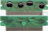
Here is my new design :
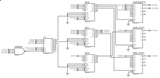
FARID wrote:
Quote:
You're decoding too much of the address, it won't be necessary for working operation
I want to remake this shitty mapper exactly. As you can see in this picture it checks A4 too
That's the spirit! Seriously though I would like to see it cloned exactly in 74 series chips.
Or in 74 series chips like Kyuusaku was saying where you have a UOROM mode.
As I said:
- don't use a '238! The active-low '138 is correct.
(You almost never see active-high in physical implementations so if you see a situation where you think it's needed you should think twice before proceeding. The reason behind this is that A-L is more efficient logically, GND is always available before the positive power rail so POR circuits require A-L, and that NMOS transistors work better than PMOS so they're able to drive their load stronger -> faster fall times and better fanout*)
- use Phi2 to STROBE the decoder, not as a select input!
The way you have it will cause logic hazards because inputs don't all arrive at the same time and of course asynchronous logic doesn't have uniform propagation, so each output will take time to settle to its correct state. This settling time more or less means glitchy outputs which will affect edge-critical things like flip-flops. If you do it the correct way with strobe, the address bits will have settled BEFORE the Phi2 phase instead of during the Phi2 phase so once strobe is asserted there will be a glitch-free output.
*totally offtopic but seems true to me: active-low is like little-endian, it's the logical way to do things given nature, but there are always people who find it inconvenient or unappealing aesthetically
---
I've talked way too much in this thread, it's probably time for me to leave it heh
So has this thing been figured out yet? I'd absolutly love to make one for my collection as there is no way in hell I'm paying the prices megaman 1 to 6 command these days. I nice homemade cart with all of them in a custom box would be lovely to play and have on my shelf
Sorry it took so long, I was busy with some other fun stuff, anyway a promise is a promise, here is the Rockman 6 in 1 cartridge. Many thanks to l_oliveira, kyuusaku, 80sFREAK, tepples and others who helped me in NESDEV IRC Channel, this wouldn't possible without their help and their invaluable information.
Chips :
27C322 --> PRG
27C040 --> CHR
6264 --> SRAM
5202 --> MMC3
174 --> Latch
4053 --> Switch
Registers :
$6800 [XXXC PLMH]
H --> D0 --> P20
M --> D1 --> P19
L --> D2 --> P18 + C18
P --> D3 --> PRG [0:256 1:512]
C --> D4 --> CHR [0:ROM 1:RAM]
All games must be Mapper 4/MMC3 [D7--- ---D0] :
Rockman 5 --> 256 + 256 --> PRG + CHR --> XXX0 0000 --> 0000 0000 --> 00
Rockman 3 --> 256 + 256 --> PRG + CHR --> XXX0 0100 --> 0000 0100 --> 04
Rockman 1 --> 256 + 8 ----> PRG + SRAM -> XXX1 0010 --> 0001 0010 --> 12
Rockman 2 --> 256 + 8 ----> PRG + SRAM -> XXX1 0110 --> 0001 0110 --> 16
Rockman 4 --> 512 + 8 ----> PRG + SRAM -> XXX1 1X01 --> 0001 1001 --> 19
Rockman 6 --> 512 + 8 ----> PRG + SRAM -> XXX1 1X11 --> 0001 1111 --> 1F
Schematic :
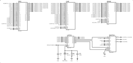
Tested on breadboard works perfect.
Here is a video to watch :
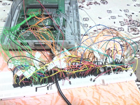
All of the chips can fit inside of a regular Famicom Cartridge :
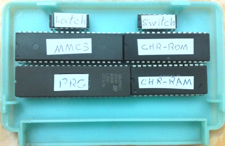 Download Menu Patch
 :
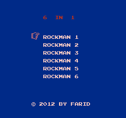
PCB :
On Progress
Farid, MAN you ROCK ! (pun is intended, too)
FARID wrote:
Seems simple enough. I'll probably make one today.
Nice work FARID! Nice to see it up and running. By the way you always have the best pictures to share of your projects
What a mess
Naiss work !
FARID wrote:
Sorry it took so long, I was busy with some other fun stuff, anyway a promise is a promise, here is the Rockman 6 in 1 cartridge. Many thanks to l_oliveira, kyuusaku, 80sFREAK, tepples and others who helped me in NESDEV IRC Channel, this wouldn't possible without their help and their invaluable information.
Chips :
27C322 --> PRG
27C040 --> CHR
6264 --> SRAM
5202 --> MMC3
174 --> Latch
4053 --> Switch
Registers :
$6800 [XXXC PLMH]
H --> D0 --> P20
M --> D1 --> P19
L --> D2 --> P18 + C18
P --> D3 --> PRG [0:256 1:512]
C --> D4 --> CHR [0:ROM 1:RAM]
All games must be Mapper 4/MMC3 [D7--- ---D0] :
Rockman 5 --> 256 + 256 --> PRG + CHR --> XXX0 0000 --> 0000 0000 --> 00
Rockman 3 --> 256 + 256 --> PRG + CHR --> XXX0 0100 --> 0000 0100 --> 04
Rockman 1 --> 256 + 8 ----> PRG + SRAM -> XXX1 0010 --> 0001 0010 --> 12
Rockman 2 --> 256 + 8 ----> PRG + SRAM -> XXX1 0110 --> 0001 0110 --> 16
Rockman 4 --> 512 + 8 ----> PRG + SRAM -> XXX1 1X01 --> 0001 1001 --> 19
Rockman 6 --> 512 + 8 ----> PRG + SRAM -> XXX1 1X11 --> 0001 1111 --> 1F
Schematic :
Tested on breadboard works perfect.
Here is a video to watch :
All of the chips can fit inside of a regular Famicom Cartridge :
Download Menu Patch :
PCB :
On Progress
Great!
The famicom is you made?
FARID wrote:
Ouch
but you cheated - patched menu
byemu wrote:
Great!
The famicom is you made?
Are you some kind of bot?
Why don't you go and learn a little english?
The translator that you are using, is the worst one! At least try to find a better translator.
Anyway, yes it is for Famicom, I always work on Famicom projects because in Iran we are using 60Pin Famicom system.
80sFREAK wrote:
Ouch
but you cheated - patched menu
No I didn't cheat. It is just my way. You want to remake this Chinese mapper. kyuusaku wants something accurate and I want a simple mapper. Each of us have our own reasons.
80sFREAK wrote:
Ouch
but you cheated - patched menu
I see no reason to mimic a pirate mapper if you can achieve the same goal with a better/simpler one.
tokumaru wrote:
80sFREAK wrote:
Ouch
but you cheated - patched menu
I see no reason to mimic a pirate mapper if you can achieve the same goal with a better/simpler one.
+1000
Even more, considering the generic nature of the pirate mapper, it's made that way so the Chinese pirate can actually save money reducing the changes he has to do to the games and making the hardware compatible with a wider range of games. That's the point on these custom variations of the MMC3 mapper. Making it simpler on a project such as this makes sense in several ways.
tokumaru wrote:
I see no reason to mimic a pirate mapper if you can achieve the same goal with a better/simpler one.
Which is, for example, why my Action 53 multicart project used oversize BxROM until the goal changed in mid-October to incorporate UNROM games.
l_oliveira wrote:
and making the hardware compatible with a wider range of games
That's the difference right there. ASIC cost considerations differ from those of homebrewers dealing with discrete 7400 series chips and CPLDs.
FARID wrote:
byemu wrote:
80sFREAK wrote:
Ouch
but you cheated - patched menu
No I didn't cheat. It is just my way. You want to remake this Chinese mapper. kyuusaku wants something accurate and I want a simple mapper. Each of us have our own reasons.
I put the smile after, so please don't treat my post as knocking down
Wow, this is awesome! I definitely want to give it a try.
i read somwhere that it should be possible to connect 2 8mbit chip as 16mbit chip for this.
can i take a 74hc139, connect it to /oe on pcb and connect the 2 /oe pins of the chips to the 74hc139, or is it done in another way?
thanks in advance:)
That likely wouldn't work. /OE is tied to ground often, and only /CE is used to select a chip.
So instead of /oe, i should connect the /ce pins of the chips to the 74hc139 and use the /ce connection on the pcb?
If you used the right logic you could use the /CE signal from the pcb socket as well as an address line to determine which of two chips to enable. The address line to use would be the one higher than the maximum size of your first chip. For example if you were using two 256Kbyte EPROMs (27c020) to simulate a 512kbyte rom, you'd use A18 on the pcb socket as the input that selects which chip gets used. I cannot give any specific wiring diagram but that is the theory behind what you are talking about.
Actually now that I think about it, if that doesn't work, you could instead use the /OE signals on the two eproms going to an IC and using both /CE and an address line as inputs to determine which EPROM should output. Either way the whole theory behind using two roms as one memory involves using external logic to take as an input one of the address lines to determine which chip should be enabled or which should output data.
You should use a menu like this
%5Bp1%5D%5B!%5D-0.png)
%5Bp1%5D-0.png)
Is more beautiful.
regards.
http://cah4e3.shedevr.org.ru/dumping_2012.php
fenix00 wrote:
You should use a menu like this
Mighty Figae Fight! My favorite game!
It is a very nice menu though, very detailed text.
recently i got my 27c322 chip and wanted to start to build my own cart, but then i noticed that my latch and switch are 74ls4053 and 74ls174. i did some research if the fact that both chips are from the ls family would work out with the project. i read that the reaction time of ls chips are lower than the one of hc chips. is this in any way bad if the chips are working at lower speed?
i ask because before i start soldering everything together i would like to know if everything is also working without any issues.
thanks in advance:)
There are other NES carts that use the LS series. It should be ok.
thanks MottZilla:)
i will try it
@ elseyf
Use breadboard or at least use IC socket, don't solder the chips directly to the PCB.
Also be careful with 27C322.
What programmer do you use for programming 27C322?
You must program it in 27C080 (8bit) mode two times :
First Half : A20 --> GND
Second Half : A20 --> +5v
The best way is to program it on a breadboard and wire Zif socket to breadboard manually.
Also ignore D8~D15 (Q8~Q15) completely as if they don't exist!
@FARID:
thanks for the tip.
I use willem pcb3.5, i will try it out.
After i got the time to work on this i am facing a problem:
When i programmed the 27C322 in 8bit mode with 27C080 settings, all i get is scrambled data from the eprom when i verify the content of it. I tripple checked all my connections of the adapter i built myself and they actually match the pinout of a 27C080 and there are no shorts. I can not figure it out what the problem is.
everything works fine when i program my flash chips, eproms and eeproms (i used all kinds upto 4mbits) in 8bit mode.
May there be an issue with voltage? I am using 5V fron USB as i do not know which adapter is used by willem pcb3 board to get myself one.
any news on a PCB for this badboy yet? My wallet is waiting to pay
Hi
Can i use 74HCT174E and 74HC4053B1?
gorgyrip wrote:
Hi
Can i use 74HCT174E and 74HC4053B1?
Yes, they are good enough, you can use them.
FARID wrote:
gorgyrip wrote:
Hi
Can i use 74HCT174E and 74HC4053B1?
Yes, they are good enough, you can use them.
Thank you. Everything it's connected. 4053 will arrive in about a week and i still need to find a 1nf cap.
gorgyrip wrote:
FARID wrote:
gorgyrip wrote:
Hi
Can i use 74HCT174E and 74HC4053B1?
Yes, they are good enough, you can use them.
Thank you. Everything it's connected. 4053 will arrive in about a week and i still need to find a 1nf cap.
1nF(102) ceramic capacitor is really easy to find everywhere :

FARID wrote:
1nF(102) ceramic capacitor is really easy to find everywhere :
I know the code, but i can't seem to find it at my local store.
Today i received the 4053 and i also found a 1nf cap (in a jamma bootleg board).
I used megaman USA roms. For megaman 1 and 2 i used this patches to convert them to mmc3:
http://acmlm.kafuka.org/board/thread.php?id=7357megaman 3 chr it's only 128k
megaman 1 prg it's only 128k
I dubbled both.
Megaman 4,5,6 works fine, but megaman 1 and 2 have huge glitches.
If i start megaman 3, press reset and select megaman1, the game has less glitches.
If i start megaman 4,5 or 6, press reset and select megaman1, the game works.
How can i fix this?
And pins 14 and 15 of 74174 and pin 7 of 4053 should i leave unconnected?
Pins 14 and 15 of 74174 --> Leave them floating
pin 7 of 4053 --> Tie it to GND
Pin 7 connected to GND, nothing changed.
I know this is the first thing i should have done, but... Anyway, I tested the patched megaman 1 and 2 roms on a tgrom board and i get the same glitches.
But why do they work on a multicart if i first start megaman 4?
Can you please look at the patches?
It sounds like your MMC3 patched versions have problems. Huge glitches is vague, but maybe mega man 1 isn't setting vertical mirroring. For Mega Man 2, maybe the same or maybe something else. Both games will never run quite the same on the MMC3.
gorgyrip wrote:
Pin 7 connected to GND, nothing changed.
I know this is the first thing i should have done, but... Anyway, I tested the patched megaman 1 and 2 roms on a tgrom board and i get the same glitches.
But why do they work on a multicart if i first start megaman 4?
Can you please look at the patches?
Have you made your multicard?
I would like to see some pictures of your project.
I extracted Rockman 1 and 2 from this rom and I didn't notice any glitch with them :
How to find the chinese siteBut for some unknown reason extracted Rockman 4 and 6 don't work so I used original ones.
gorgyrip wrote:
But why do they work on a multicart if i first start megaman 4?
The hacks might not be performing a full mapper initialization (for example, you shouldn't expect the 8KB of CHR-RAM to be mapped linearly on power up, you have to map them in the correct order in software), but Mega Man 4 does it.
What i mean by glitches is that the game is working, but it's full of graphical glitches.
Megaman1 titlescreen:
Attachment:
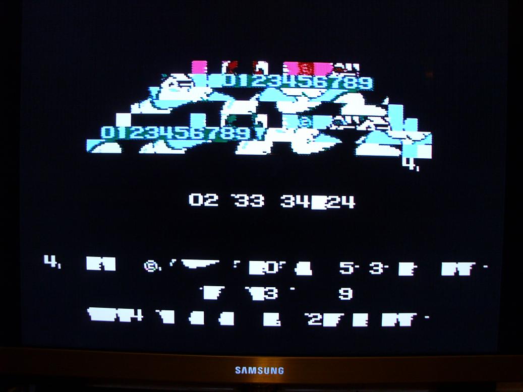 IMG_3191.JPG [ 74.26 KiB | Viewed 3515 times ]
Megaman1 stage select:
Attachment:
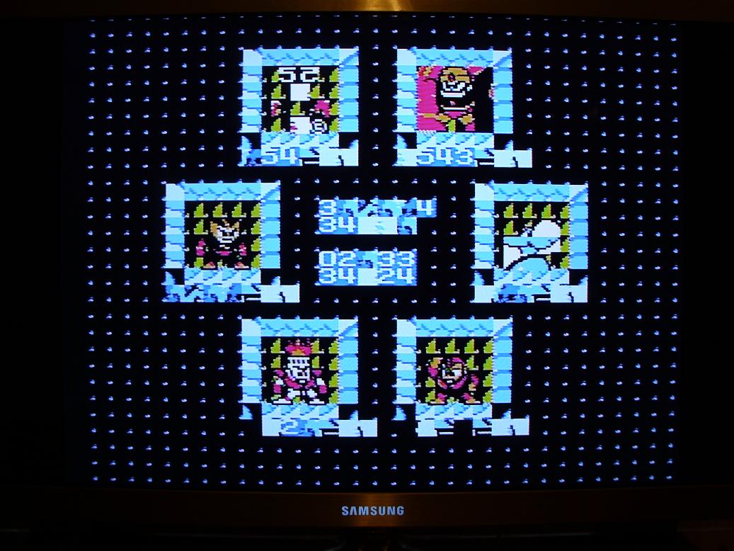 IMG_3192.JPG [ 136 KiB | Viewed 3515 times ]
Megaman1:
Attachment:
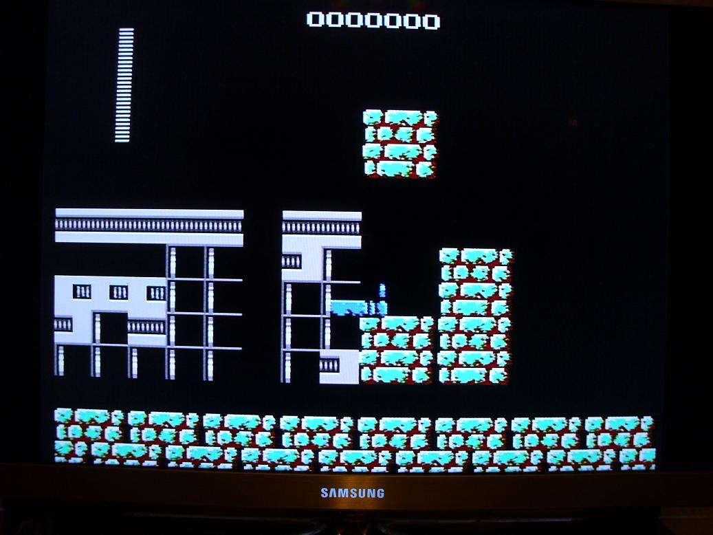 IMG_3193.JPG [ 99.19 KiB | Viewed 3515 times ]
It would be great if someone modify these mmc3 patches for megaman 1 and 2 to work on real hardware:
http://acmlm.kafuka.org/board/thread.php?id=7357Farid, i will post pictures of my cart.
I used official USA Megaman roms and used the above patches for megaman 1 and 2.
Btw, i also tested rockman1 + mmc3 patch (the one posted on romhacking by jpx) on a tgrom board and it's working.
tokumaru wrote:
gorgyrip wrote:
But why do they work on a multicart if i first start megaman 4?
The hacks might not be performing a full mapper initialization (for example, you shouldn't expect the 8KB of CHR-RAM to be mapped linearly on power up, you have to map them in the correct order in software), but Mega Man 4 does it.
This definitely looks to be the case. Your Mega Man hacks expect CHR-RAM is a linear 8KB memory. But on MMC3 you can bankswitch CHR-RAM. You could get around this if the menu initialized the CHR registers though.
So can you please modify the menu or the patches?
PS: i also noticed that the music in megaman2 it's kind of strange, like distorted.
FARID, here are the pics:
Attachment:
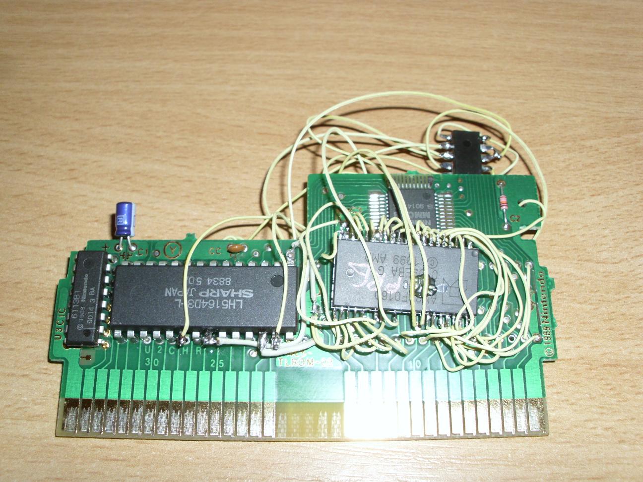 cart front.jpg [ 205.45 KiB | Viewed 3512 times ]
Attachment:
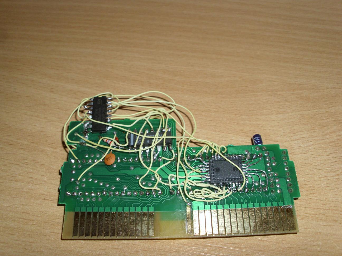 cart back.jpg [ 185.42 KiB | Viewed 3512 times ]
Nice Work, Good Job, Well Done!
What parts have you used for the board?
Also I don't see any 102 cap.
Can you tell me the specification of other original caps of the board?
Use this patch and see if it works for you :
Rockman 1 & 2 MMC3 PatchBut always use IC socket and never put solder on the pins of the ICs.
Thank you:
the parts i used:
board: TLROM
prg: 29F016 so44
chr: 49F040 plcc32
sram: LH5164D3-L
M74HC4053B1
CD74HCT174E
original caps on the board: ceramic 221; 22uf/6.3v
You don't see any 102 cap because the pics are taken before i found the cap on jamma board. But it make no difference if i was the cap or not. But if i use an 100nf cap, only megaman 5 will work.
Thank you for the patches, but i need patches for megaman, not rockman.
Weird, i applied rockman1 patch to usa megaman1 and it seems to work in nestopia. I will try it also on real hardware and let you know.
EDIT: IT Works! Megaman 1 works with rockman1 mmc3 patch on real hardware.
I've beated the entire game and everything it's ok.
The only problem i found was at the title screen, but i fixed it:
Attachment:
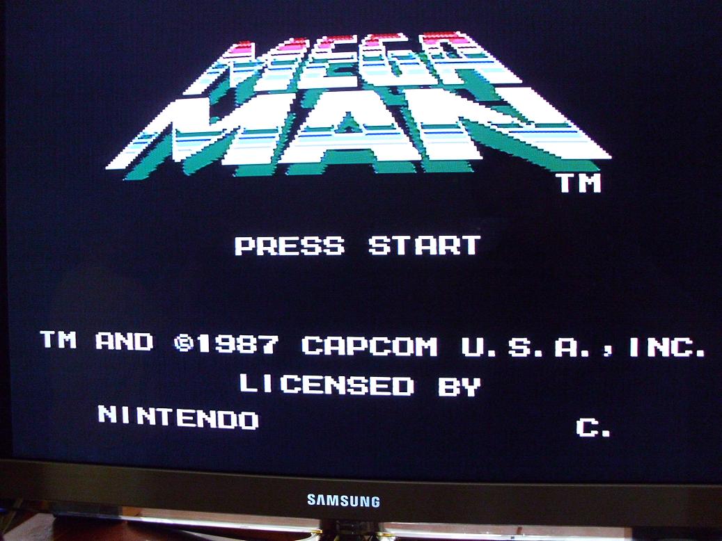 title.jpg [ 112.34 KiB | Viewed 3488 times ]
So megaman 1 problem is solved.
Now i only need a mmc3 patch for megaman 2.
gorgyrip, please check my thread back in acmlm, I fixed my megaman 2 patch, along with megaman, contra, castlevania, duck tales, legend of zelda.
Thank you. I've just replyed there. Tested and working GREAT!
infidelity wrote:
gorgyrip, please check my thread back in acmlm, I fixed my megaman 2 patch, along with megaman, contra, castlevania, duck tales, legend of zelda.
Thanks for the efforts
I am waiting for Captain Tsubasa and Ninja Gaiden to be converted to MMC3 as well
Also please make a tutorial for MMC1 to MMC3 conversion so that I can help you with this kind of stuff
Ooooh, Ninja Gaiden, I love that game. Tonight ill take a look at that one.
If you look at my notes for the mmc1 games I converted, it should give you some what of a template/idea of what to do.
Basicly I first start by changing the mapper to mmc3 with "neshead" Then I find where the mmc1 bankswap takes place, and at that point, I insert a jsr overwriting the old bankswap, to jump to the proper mmc3 bankswap routine. Then once the game boots, I begin to fix the mirroring. For this to work on the nes, I had to insert the proper $8001 chr setup within the reset vector, you can find that in my notes, like Megaman 2's notes I wrote.
@ infidelity
Thanks for the brief explanation
But please write a complete tutorial by using a game as an example
Something like KingMike's DTE tutorial would be great
FARID I am working on a MMC3 Multicart (TSROM hardware). I was going to make it work using the clock signal to increment a digital counter to select the banks I am putting each game in... But I figured I should ask you, did you make a menu program for MMC3 games?
I've replaced PRG. Now Megaman 1 and 2 are working. But I still have problems with Megaman 2. The sound is distorted. What should i do? It's not the mmc3 patch because i tested it on a tgrom board.
How badly is the sound distorted? Mega man 2 normally has noise in some music. Crashman stage is a good example.
Movax12 wrote:
How badly is the sound distorted? Mega man 2 normally has noise in some music. Crashman stage is a good example.
Really bad. All the sound is distorted. The intro, title screen, gameplay.
Here's a sample. Sorry about the quality, but please listen carefully:
http://www.youtube.com/watch?v=bV7jRx3h ... e=youtu.be
GameMachineJames wrote:
FARID I am working on a MMC3 Multicart (TSROM hardware). I was going to make it work using the clock signal to increment a digital counter to select the banks I am putting each game in... But I figured I should ask you, did you make a menu program for MMC3 games?
Now we are on the right direction! Yeeeeee Haaaaaaa!
Oh sheee. what did you say?
TSROM and it means we have PRG-RAM also!
Now it is a little tricky.
Another interesting challenge!
How are you going to generate the clock signal?
And yeah I possess a powerful TLROM Multicard menu but it just work with WRAM /CE as a clock signal on STA $6000~7FFF
But no I didn't write it
I dumped it from a real pirate glop top cartridge which was Kunio Nekketsu 8 in 1
What games do you want to put on the multicart?
Super Mario Bros.
Super Mario Bros. 2j
Super Mario Bros. 2
Super Mario Bros. 3
(Those first two are hacks doppel made for me that run as MMC3.)
I can't give the ROMs out, but to make my own personal cartridge yes.
I am currently using the clock signal from the CIC to count "up" my timer and increment as a game switch. It works by resetting the system, each time it chooses a different bank on boot.
So the mm2 audio issue is not present on the tgrom board, am I reading that right?
Working on Metroid MMC3 conversion today.
UPDATE - I now have Metroid converted to mmc3. Boots/plays on FCEUX, Nestopia, Nintendulator, and on a real nes.
I will now attempt converting Ninja Gaiden to mmc3. Hoping I can pull it off.
infidelity wrote:
I will now attempt converting Ninja Gaiden to mmc3. Hoping I can pull it off.
Please write some tips along the way, I am really interested in learning it. Thanks in advance
infidelity wrote:
So the mm2 audio issue is not present on the tgrom board, am I reading that right?
You are correct. The audio problem it's only present in a multicart.
I remember reading that Capcom's music engine never initializes the sweep register. Try inserting LDA #$00 STA $4001 STA $4005 before the game starts.
tepples wrote:
I remember reading that Capcom's music engine never initializes the sweep register. Try inserting LDA #$00 STA $4001 STA $4005 before the game starts.
I'm sorry, but i don't know what that means. Maybe Farid or Infidelity can help me with that.
Id say insert that code within the reset vector.
"A900 8D0140 8D0540"
If you are unable to do this, I might have time tonight to insert into mm2, and send you the patch to see if that fixes the sound issue on your multicart.
infidelity wrote:
Id say insert that code within the reset vector.
"A900 8D0140 8D0540"
If you are unable to do this, I might have time tonight to insert into mm2, and send you the patch to see if that fixes the sound issue on your multicart.
Please do that for me. I've tested all your mmc3 patches on a cart board. I it's better to post the results on the forum you released them.
gorgyrip wrote:
tepples wrote:
I remember reading that Capcom's music engine never initializes the sweep register. Try inserting LDA #$00 STA $4001 STA $4005 before the game starts.
I'm sorry, but i don't know what that means. Maybe Farid or Infidelity can help me with that.
Do this :
Run the game with FCEUX
Debug --> Hex Editor
Scroll down to the end of list
E0 FF at the end line is called reset vector
Reset vector points to the $FFE0
Find that address, it is just a line above
Hopefully there are some free bytes before $FFE0
Insert the suggested code there : A9 00 8D 01 40 8D 05 40
Now change the reset vector to D8 FF so that it points to $FFD8 which is the start of our new code
The result would be like this :

By the way you need to edit these value within the ROM so every time you want to edit a value right click on it and select "Go Here In Rom File"
You can switch between ROM File and NES memory from view menu on the menu bar of the hex editor
Don't forget to save it before exiting File --> Save Rom
I made the changes, but i still have audio distorsion. I also noticed that if i start megaman 2, reset the console and select megaman 1, megaman 1 will also have audio distorsion.
EDIT: I did another test. I've replaced Megaman 1,2,4,6 PRG with megaman 2 PRG. Megaman 2 placed in slot 1 has no audio distorsion, but in slots 2,4,6 has audio distorsion.
Farid, can you please modify your menu so slot 2 will be similar to slot 1?
gorgyrip, please check acmlm board. Ive updated all my unrom to mmc3 patches with proper mirroring setups. I think its all set.
Also, Metroid has been added to my mmc3 coverted patch set.
-infidelity
gorgyrip wrote:
Farid, can you please modify your menu so slot 2 will be similar to slot 1?
All of those slots are the same, except first slot which is Rockman 5 and there is no way to swap it with other slots, because it is hosted multicart menu routine.
Can you test and see if swapping rockman 1 and 2 would solve you problem?
So that whenever you select rockman 1 at the menu, rockman 2 would start and by selecting rockman 2 you would have rockman 1
I've swaped megaman 1 with megaman 2. Now megaman 1 has audio distorsion and Megaman 2 has perfect audio. In this case for megaman1 i've used Farid's patch and for megaman 2 i've used Infidelity's patch.
Note: if i first start megaman 1, reset and start megaman 2, the game will also have audio distorsion.
Another test: megaman 1 and 2, both with infidelity's patch. Both have audio distorsion.
Just wanted to give an update on Ninja Gaiden to mmc3. Progress is slowly coming along. This conversion has proved to be more difficult than all the rest. Ill give a more thorough explaination when I get the chance, but what I can tell you is that rom does boot up as mmc3, but chr/mirroring are 2 major factors that I need to tackle. Im fixing them, making progress.
Another test (i'm going crazy here).
I replaced Megaman 1,2,4,6 with castlevania mmc3. Castlevania works perfectly, no matter wich one i start.
Now i only replaced megaman 1,2 and 4 with Castlevania mmc3. Castlevania starts, but after the intro (when he enters the gate), i get a black screen, no matter wich game i select.
Next I replaced Megaman 1,2 and 6 with castlevania mmc3. Castlevania works perfectly, no matter wich one i start.
So, it's something wrong with my wiring or with the menu?
Ninja Gaiden MMC3 is about 95% complete. Need to figure how to have the text for both the cutscenes and the in-game hud, to display correctly. The text shows up as whatever tiles are stored currently in the ppu, they get fetched from somewhere else in the rom. Its been a long time since ive worked with something like this. I had to rewrite how $8000-$8001 read gaiden's chr setup. But when I try to have 2 sets of routines, the in-game palette fade in gets stuck in a weird loop, and the chr routine doesnt work. This is the only issue left with this game from becoming a full MMC3 port.
EDIT - Freak luck, I was able to get the text to appear for the cutscenes.
Now im still trying to decypher in-game co-existences of 2 chr setups, very difficult.
EDIT #2 - Making progress, found a workaround but it aint pretty looking code wise, but its being allowed to work and display. Hoping by tonight or tomorrow to have it finished.
Ok, I have Ninja Gaiden working as MMC3.
Tested and working on the following emulators.
FCEUX
Nestopia
Nintendulator (with some shaking issues. Can others please confirm?)
Also tested and working on my RetroPak for my NES.
Ive only played up to Act III on all devices. But everything leading up to Act III, (title screen, cutscenes, level layouts, mappings, etc) are all there and correct.
I do not have a tkrom board/multirom board, nor the proper tools for that, so I cant confirm if my patched work will work on those devices.
My MMC3 Package Now Updated To 4.0, Which Now Includes Ninja Gaiden Converted To MMC3, Along With Noteshttp://acmlm.kafuka.org/uploader/get.php?id=4456 I hope you all enjoy this, this really was more work than I expected! :-0
-infidelity
Workin on a guide on how I convert (specificly) towards MMC1 to MMC3, regarding CHR, and bankswapping.
@ infidelity
Well done, thank you!
Now it is possible to make the Ninja Gaiden Trilogy multicart!
Also thank you for the tips, that is really awesome.
Keep up the good work.
FARID wrote:
@ infidelity
Well done, thank you!
Now it is possible to make the Ninja Gaiden Trilogy multicart!
Also thank you for the tips, that is really awesome.
Keep up the good work.
that would be awesome
you could do it like on the SNES and put in some pictures if it is not too hard
Farid, have you made the ninja gaiden multicart?
So anyone got a PCB in the works for this as of yet?
I don't think there will ever be a PCB available because it's not cost effective.
The best way is to use adapters. TSOP and SO chips are not expensive and after that use wires.
I still didn't solved the audio issue in megaman 2. FARID teste it on a famiclone, maybe doesn't work right on an original nes, or maybe i did something wrong (i checked everything many times) or maybe the blame is on the 74 chips.
FARID said at one moment that had in mind a ninja gaiden trilogy. That will be easyer to build because each game has only 128k chr and 128k prg, so you can use 2x 29f040, dip32.
gorgyrip wrote:
I don't think there will ever be a PCB available because it's not cost effective.
The best way is to use adapters. TSOP and SO chips are not expensive and after that use wires.
I still didn't solved the audio issue in megaman 2. FARID teste it on a famiclone, maybe doesn't work right on an original nes, or maybe i did something wrong (i checked everything many times) or maybe the blame is on the 74 chips.
FARID said at one moment that had in mind a ninja gaiden trilogy. That will be easyer to build because each game has only 128k chr and 128k prg, so you can use 2x 29f040, dip32.
I don't understand how it wouldn't be cost effective as it's still gonna use the exact same amount of chips no matter what and you don't need to to use tsop adapters if you stick to a 27c160 in 8bit mode. It would just be nice to not have to make a rats nest of wires and chips to get it done is all and I believe this project to be popular enough that it would justify making a pcb for it.
Yeah I agree with gorgyrip
Making the cartridge at home is more cost effective than ordering a small quantity of the PCB
By the way I made the PCB design long time ago but I can't release it until I test it myself and the problem is I don't have free time to do that :

nintendo2600 wrote:
gorgyrip wrote:
I don't think there will ever be a PCB available because it's not cost effective.
The best way is to use adapters. TSOP and SO chips are not expensive and after that use wires.
I still didn't solved the audio issue in megaman 2. FARID teste it on a famiclone, maybe doesn't work right on an original nes, or maybe i did something wrong (i checked everything many times) or maybe the blame is on the 74 chips.
FARID said at one moment that had in mind a ninja gaiden trilogy. That will be easyer to build because each game has only 128k chr and 128k prg, so you can use 2x 29f040, dip32.
I don't understand how it wouldn't be cost effective as it's still gonna use the exact same amount of chips no matter what and you don't need to to use tsop adapters if you stick to a 27c160 in 8bit mode. It would just be nice to not have to make a rats nest of wires and chips to get it done is all and I believe this project to be popular enough that it would justify making a pcb for it.
If you think it's cost effective, DO IT YOURSELF
P.S. we can talk about it from 30 buck shipped(per one) in a run of 50. Bare PCB
80sFREAK wrote:
nintendo2600 wrote:
gorgyrip wrote:
I don't think there will ever be a PCB available because it's not cost effective.
The best way is to use adapters. TSOP and SO chips are not expensive and after that use wires.
I still didn't solved the audio issue in megaman 2. FARID teste it on a famiclone, maybe doesn't work right on an original nes, or maybe i did something wrong (i checked everything many times) or maybe the blame is on the 74 chips.
FARID said at one moment that had in mind a ninja gaiden trilogy. That will be easyer to build because each game has only 128k chr and 128k prg, so you can use 2x 29f040, dip32.
I don't understand how it wouldn't be cost effective as it's still gonna use the exact same amount of chips no matter what and you don't need to to use tsop adapters if you stick to a 27c160 in 8bit mode. It would just be nice to not have to make a rats nest of wires and chips to get it done is all and I believe this project to be popular enough that it would justify making a pcb for it.
If you think it's cost effective, DO IT YOURSELF
P.S. we can talk about it from 30 buck shipped(per one) in a run of 50. Bare PCB
^ I'd buy one. Just to make fixing my Rockman cart easier. Also, 80sFREAK is a good guy to work with. I've bought stuff from him via Famicom World.
80sFREAK wrote:
I don't understand how it wouldn't be cost effective as it's still gonna use the exact same amount of chips no matter what and you don't need to to use tsop adapters if you stick to a 27c160 in 8bit mode. It would just be nice to not have to make a rats nest of wires and chips to get it done is all and I believe this project to be popular enough that it would justify making a pcb for it.
If you think it's cost effective, DO IT YOURSELF
P.S. we can talk about it from 30 buck shipped(per one) in a run of 50. Bare PCB
[/quote]
I don't think it would be $30 a bare PCB. There are plenty of small fab company in China that do small runs for ALOT less
than that. I've had my hands on my pcbs from these places for the atari machines (2600, 7800 & 5200). Prices ranged from
around $1.25 to $5 a board pending the size of the board and how many are ordered. If you get a few hundred boards made
the price is pretty darn cheap if you plan on selling at least enough to cover the costs of the boards (not talking about the cash
value of the persons time to draw the pcb as thats a totally different monster). Hell I have got them by the box full in the past
with 9 boards per sheet. Silk screened logos the whole 9, but I just paid for them, I didn't do the gerber files as I'm not good
with gerber\egale\whatever software to draw the board and it's layers.
Here is my updated patch set. I also included an mmc1 doc, im no expert, but ive had some success.
http://acmlm.kafuka.org/uploader/get.php?id=4475
Teancum wrote:
Thankyou very much for the menu. Let me start by saying I am very new to this. I applied the patch to Mega Man V (USA) version. I opened it with FCEUX and your menu appears. I then select "Rockman 5" from the menu and the game starts!
I'm not sure how to add the other games though. I see on your post you put.
"All games must be Mapper 4/MMC3 [D7--- ---D0] :
Rockman 5 --> 256 + 256 --> PRG + CHR --> XXX0 0000 --> 0000 0000 --> 00
Rockman 3 --> 256 + 256 --> PRG + CHR --> XXX0 0100 --> 0000 0100 --> 04
Rockman 1 --> 256 + 8 ----> PRG + SRAM -> XXX1 0010 --> 0001 0010 --> 12
Rockman 2 --> 256 + 8 ----> PRG + SRAM -> XXX1 0110 --> 0001 0110 --> 16
Rockman 4 --> 512 + 8 ----> PRG + SRAM -> XXX1 1X01 --> 0001 1001 --> 19
Rockman 6 --> 512 + 8 ----> PRG + SRAM -> XXX1 1X11 --> 0001 1111 --> 1F"
I attempt to add Rockman 3 to the end of Rockman 5 (I used the copy command on Windows. "copy /b MM5+mm3 MM16.nes" However this doesn't seem to work for me. Should this be all one rom that I can get to work on an emulator?
Thanks for your patience.
You have to use ReadNES3 to split the roms then use HxD to join the files :
PRG.bin Structure file :
Rockman 5 PRG
Rockman 3 PRG
Rockman 1 PRG
Rockman 2 PRG
Rockman 4 PRG
Rockman 6 PRG
CHR.bin Structure file :
Rockman 5 CHR
Rockman 3 CHR
Then you should program PRG.bin and CHR.bin to EPROMs...
If you are new to this, maybe you should start with a more simple project like this one :
Super Mario All-Stars NES Multicart Build
These Rockman/Megaman 6 in 1 carts are more prolific now and I decided to try one off of aliexpress.
specifically:
http://www.aliexpress.com/item/Megaman- ... 44e59b955cA couple of points worth noting here is that this does not function properly on clone hardware. I have a Tri Star Super 8 unit which piggy-backs off a SNES and a few games locked up and would not proceed: MM3, MM6
On original hardware there are no issues and everything works as specified. The issue comes up when speaking about the sound processing of MM1 & 2. Whether on clone or real hardware both games have distortion and thats why I am ultimately posting with respect to this.
Here is an example of the sound troubles on a similar bootleg (pardon the 50hz speed):
https://youtu.be/523qkDi1Zyw?t=53 (also, check the video in the aliexpress link for samples)
I have no background as to the cause pardon searching and seeing the notes regarding the registers [
#115318]. I also wondered if there was a conflict with the mappers and rom types not being implemented properly on cartridge.
All the same, there are cases where the sound is not distorted on MM multi-carts:
https://youtu.be/NOJOX88UHTw?t=170The issue isn't that the Rockman roms are different from the Megaman roms in the mapper department as I learned so I wondered exactly why this issue exists and what can possibly be done to remedy it. Here is further information as I found elsewhere on the exact circuit board in place on these bootlegs:
Quote:
Ok on the battery side the chip says:
HSRM20255LM10
F31M 271
Japan
The text in the upper left corner says "Pocket games" which seems to be the brand name of these boards.
As you can see there is what looks like a place to connect a chip as well as a few dip points. The one on the right hand side of the battery is closed. The one next to the chip looks like a solid blob in my cruddy pic, but it's actually 3, and the top two are closed together. It's labeled "j8".
---------------------------------------
The back of the pcb:
It says UNION at the top... it appears to be the pcb manufacturer. The serial on the upper right reads: SMD157D-72 (72 most likely stands for 72 pin as there is a famicom version of this cart). The large white text in the lower right says SMD151212.
On the top left hand side there are solder points for what looks like a diode, a dip and another diode respectively labeled D1 R1 and D2. Since it's labeled R1 maybe the dip is actually a spot for a resistor?
There is a blank spot for a chip on the left labeled U6 and a chip labeled U9 below it.
The large chip to the left is labeled U3 and reads:
MXIC 81325
29GL256EHMC-90Q
3P060800
TAIWAN
The square chip in the center is labeled U1 and reads:
SMD132
2015.11.18
The solder pads (for a dip) to the left of that chip are labeled 5/6K. The one below and to the right is labeled H/V (the rom order dip). The rest of the dip pads on this side of the pcb are unlabeled.
imgs:
http://i.imgur.com/4htrpG1.jpg http://i.imgur.com/j45bo6b.jpg
fahlim003 wrote:
These Rockman/Megaman 6 in 1 carts are more prolific now and I decided to try one off of aliexpress.
specifically:
http://www.aliexpress.com/item/Megaman- ... 44e59b955cA couple of points worth noting here is that this does not function properly on clone hardware. I have a Tri Star Super 8 unit which piggy-backs off a SNES and a few games locked up and would not proceed: MM3, MM6
On original hardware there are no issues and everything works as specified. The issue comes up when speaking about the sound processing of MM1 & 2. Whether on clone or real hardware both games have distortion and thats why I am ultimately posting with respect to this.
Here is an example of the sound troubles on a similar bootleg (pardon the 50hz speed):
https://youtu.be/523qkDi1Zyw?t=53 (also, check the video in the aliexpress link for samples)
I have no background as to the cause pardon searching and seeing the notes regarding the registers [
#115318]. I also wondered if there was a conflict with the mappers and rom types not being implemented properly on cartridge.
All the same, there are cases where the sound is not distorted on MM multi-carts:
https://youtu.be/NOJOX88UHTw?t=170The issue isn't that the Rockman roms are different from the Megaman roms in the mapper department as I learned so I wondered exactly why this issue exists and what can possibly be done to remedy it. Here is further information as I found elsewhere on the exact circuit board in place on these bootlegs:
Quote:
Ok on the battery side the chip says:
HSRM20255LM10
F31M 271
Japan
The text in the upper left corner says "Pocket games" which seems to be the brand name of these boards.
As you can see there is what looks like a place to connect a chip as well as a few dip points. The one on the right hand side of the battery is closed. The one next to the chip looks like a solid blob in my cruddy pic, but it's actually 3, and the top two are closed together. It's labeled "j8".
---------------------------------------
The back of the pcb:
It says UNION at the top... it appears to be the pcb manufacturer. The serial on the upper right reads: SMD157D-72 (72 most likely stands for 72 pin as there is a famicom version of this cart). The large white text in the lower right says SMD151212.
On the top left hand side there are solder points for what looks like a diode, a dip and another diode respectively labeled D1 R1 and D2. Since it's labeled R1 maybe the dip is actually a spot for a resistor?
There is a blank spot for a chip on the left labeled U6 and a chip labeled U9 below it.
The large chip to the left is labeled U3 and reads:
MXIC 81325
29GL256EHMC-90Q
3P060800
TAIWAN
The square chip in the center is labeled U1 and reads:
SMD132
2015.11.18
The solder pads (for a dip) to the left of that chip are labeled 5/6K. The one below and to the right is labeled H/V (the rom order dip). The rest of the dip pads on this side of the pcb are unlabeled.
imgs:
http://i.imgur.com/4htrpG1.jpg http://i.imgur.com/j45bo6b.jpgWere you ever able to solve this issue? I have this same multicart and I would like to get the sound working properly for mega man 1 and 2. If you are able to fix it, could you please share your patched rom so that I can have it burned to my cart?


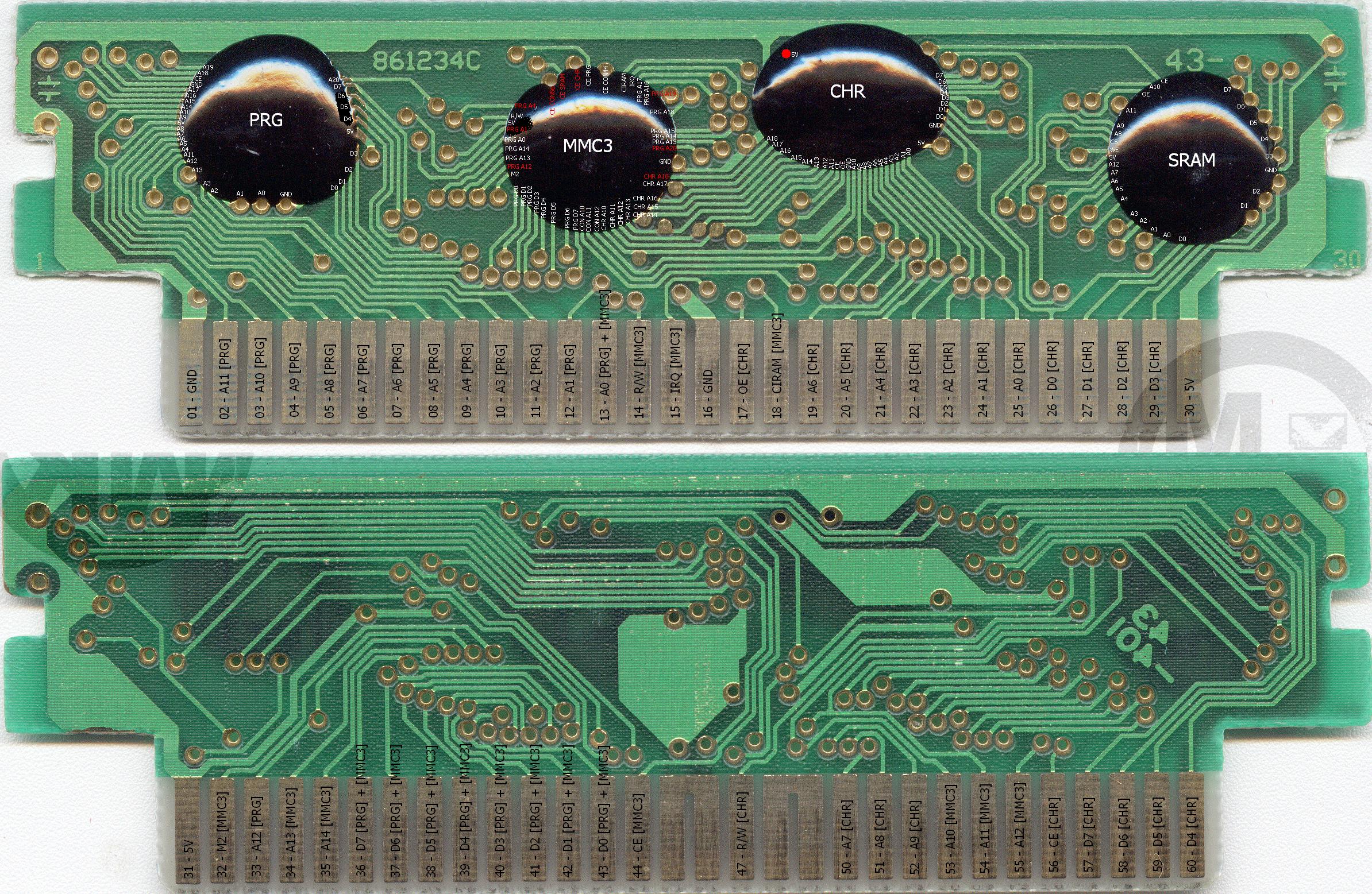
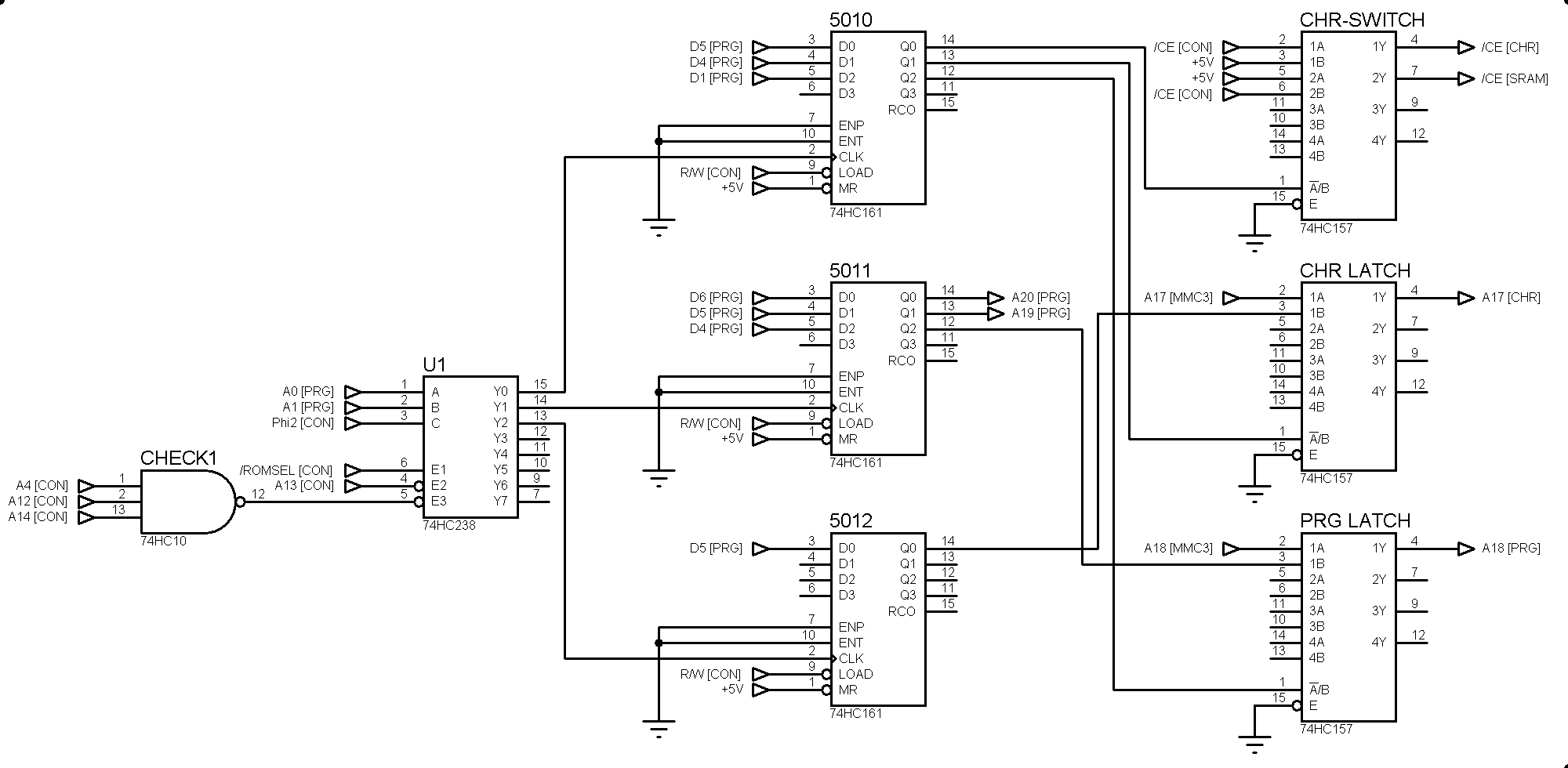


