So I've acquired access to the use of a power glove, and I've decided to research its operation, since I can't find proper documentation on it. I mean, there's all sorts of stuff out on the internal functioning, but not from a NES programmer's point of view. What interests me the most is the games that (apparently) send their own custom configuration to the glove, separate from the 14 preprogrammed settings; the only one I know of being Bad Street Brawler. As I type this I realize I should probably be dowloading and disassembling the rom and looking for code around $4016/7 accesses but it might not be that simple. Any suggestions for writing a Power Glove test ROM?
and why does the NES controller port pinout on the wiki redirect to itself?
Oops, my bad. Fixed.
can anyone help me figure out what this chart means? you can skip the basics, I just want to figure out how to use this information.

"LATCH" is the last value WRITTEN to D0 of $4016.
"CLOCK" pulses happen whenever $4016 is READ. At that point, the CPU samples the state of lines D0, D3, and D4 from the controller; do you have traces of those?
For a standard controller, LATCH goes 1 then 0, followed by 8 clocks, as seen in the data packet.
But what's happening in this init sequence is the NES sending data to the controller.
A bit deletion due to DPCM on this sort of stream would be a pain.
tepples wrote:
A bit deletion due to DPCM on this sort of stream would be a pain.
That's good to know...if I ever plan to use the glove beyond visual-only programs, I'll remember to take caution with the DPCM channel or not use it at all. Do you think it's necessary to wait the exact number of microseconds as specified in the diagram, or am I not understanding it correctly? Could it just be a measurement of some natural function of the NES, or some arbitrary measurement from a specific game?
The -LATCH pulses with duration on the order of 10000 µs are probably a wait just less than a frame, as 16640 µs = 1 NTSC NES frame. The +LATCH pulses on the order of 1000 µs are probably just a couple thousand CPU cycles, just long enough to show that it's not a regular controller.
It'd be possible to make a timing circuit to clean up clock signal distortions caused by the DPCM channel's DMA unit, much like the timing circuit in the MMC3's scanline counter that spreads A12 pulses. I wonder whether the glove has one.
It'd be possible to make a timing circuit to clean up clock signal distortions caused by the DPCM channel's DMA unit, much like the timing circuit in the MMC3's scanline counter that spreads A12 pulses. I wonder whether the glove has one.
OMG necrobump! (sorry, mods)
Did this exploration ever turn into anything? I'm contemplating poking around with a Power Glove myself, and while other sources like http://textfiles.fisher.hu/programming/gla-91o and http://wiki.hak5.org/index.php?title=Episode_2x03 do support the idea that the output of the glove is deterministic and meaningful and that the startup sequence is reproducible, those time delays do seem both arbitrary and difficult to get out of a NES.
I would accept that the init sequence listens for 4 clocks, then a low->high->low latch followed by 7 bytes of data and a final latch hold/release, and I would accept that the hardware in the glove may only buffer 8 bytes at a time and thus require 2 frames to fully deliver a packet. I'm curious what the tolerances are on those 7212µs, 2260µs and 892µs waits are, though. Specific times keyed to some timer in the glove? Just arbitrary values someone pulled with a scope from Super Glove Ball representing the particular code that game ran? If I were to just NMIwait a full frame for each, would it still work, or are instruction-timing loops to precise µs values really needed?
Quote:
*crickets chirp*
Okay. I'll take that as a "no."
I'm still going to take a swing at it, and I might as well throw my thoughts here.
From an interface perspective, I'm guessing the design was not SO pathological as to require cycle-precise timing to initialize the glove. Worst-case scenario I may need to disassemble Super Glove Ball and just yank its code between those first 4 $4016 reads and wherever I can pin down the end of that sequence being, but...
From an electrical engineering perspective, I doubt that initial latch low/high hold is being timed explicitly on the glove. Building in timing hardware specifically to prevent people who didn't know to wait precisely 7212µs / 2260µs would be pathological and expensive and easily defeated by some college kid with a good scope. I suspect this is just a function of the setup code of whatever game the trace was recorded from, and for my first pass, I plan to just 4-clock, NMIwait, latch up, NMIwait, latch down and go. If that fails, I can always add code. Having some pause in there is probably a good thing- crunchy semi-analog electronics are likely to need some time to warm up or enter steady-state after being activated, but I will be surprised and depressed if the precise wait times are really required. Also, those first 4 clocks? I'm guessing that's the game "asking" whatever's connected whether it's a Glove. This would make more sense if, say, regular pads returned up/down/left/right bits first and the game could check whether, say, up and down were simultaneously held (if so, probably not a regular pad), but even so, who holds A+B+Start+Select at startup? This may still be what was showing up on the trace, we'll never know what the game was doing with the returned bits. If so, it may not even be a required part of the init- the init may begin with the long hold of the latch, or even with the first clock/poll that (unusually) occurs with the latch still raised.
From a low-level architectural programming perspective, the poster in that newsgroup snapshot who states
Quote:
Well, if anyone is interested, the 7 bytes sent to init the glove seem
to be: 0x06, 0xC1, 0x08, 0x00, 0x02, 0xFF, 0x01
to be: 0x06, 0xC1, 0x08, 0x00, 0x02, 0xFF, 0x01
probably has the right idea, and even the right interpretation of the bytes. My 2 cents as to how that message breaks down is not that it's a "program" per se, but rather a configuration, bookended with the sorts of things you'd want as a Glove-side engineer to verify the message was correct. To wit, I would propose
$06: "6 bytes of data will be included in this packet"
$C1 $08 $00 $02: "go into manual-override mode and start sending me packets conforming to these parameters:..." (no clue what each byte individually represents... $08 may be bits-precision-on-position, $C1 may be as simple as "12-position angular resolution, data returned in steps of 1", but really I'm just taking stabs in the dark. the $C may also refer to 12 bytes of data in the return packet, or the $8 may be requesting 8-ish bytes of non-"junk" data in the return. $00 $02 may be 2's complement on the position data with 0 as center. The world may never know.)
$FF: "here's an easily-identifiable stop-byte. Message ends."
$01: "The message I sent should have checksum $01, if it doesn't you missed something" (or, meh, this may be real data on the order of $FF-range precision in units of $01, or in $01 byte per axis)
If I'm on the right track, posterity may just need to sit back and accept the 2-frame 12-byte packets half full of "junk" because I have no thoughts on what the checksum algo might be (other than that it can probably be computed sequentially bit by bit and take up no more than 1 byte of Glove-side memory. Could it be as simple as an odd/even sum result of the pre-stopbyte bytes? Or an odd/even count of 1s in the bitstream?) Anyway, without cracking the checksum, the Glove would probably reject any variation to the 4 real parameters.
And the "junk" bytes in the return packet? Probably not strictly junk. It would be appallingly wasteful to force NES developers to take a 50% hit in sampling rate when all the "good" data is in the first 8 bytes. I think the newsgroup also observed the last byte seems to correlate to whether or not the glove is pointed at the speaker array. If it's something as crazy-straightforward as the levels/timings the mics are detecting, it really would look kinda like noise and be ultimately unuseful save in some explicitly designed cases. It may also be that the data packet in "hi-res" mode is 12 bytes always regardless, and the particular hi-res configuration sent to the glove only uses 6-7 of them, with the rest reserved in case of later need. If the return packet isn't fixed-at-12-bytes because of potential data usage, the only other explanation I can think of is that the glove itself needs X amount of time to sample its hardware and may force the NES dev to poll it a few extra times before it's required to return real data just so it has time to get its bits in order. Glove-side register timing is one likely candidate for that blatant vblank wait after the first 8 bytes- if the glove has only 8 regs lined up for data output, it probably needs a breather to shift the remaining 4 bytes in. Still, if I get as far as seeing any data out of the glove, I'll probably test it with the delay and with trying to grab all 12 bytes in one frame.
OR we could turn the Glove-needs-time hypothesis inside out and posit that perhaps the 12-byte return is an artifact rather than an intent: it may be that the glove takes Xµs to get a new frame of data any which way, whether it's polled 8 times, 12 times, or 100 times in the interim, and at that wonderful timing everyone's reproduced from that trace diagram, there just happen to be 11 samples between the header byte marking the start of real data and the header byte marking the next start of real data. This would be consistent with observations on the newsgroup that the first bytes out of the glove came from the middle of the "packet": Glove don't care. Glove gonna put Glove's data on the line when Glove's ready, regardless of what big Mr. NES coder's timeline is. It's the game's job to listen for the header byte and jump into the datastream when Glove says so.
But until I get my just-ordered flashcart and start dumping some builds to hardware, I won't really know a thing. And when/if I do get data off the glove onto the NES, I'll try to keep the board updated.
LoneKiltedNinja wrote:
From an electrical engineering perspective, I doubt that initial latch low/high hold is being timed explicitly on the glove..
True, the Super NES Mouse is widely thought to require somewhat specific timing: 16 bits fast, then a delay, than 16 bits slow, to match what Mario Paint does. But it's just an SPI device like any other Super NES controller, and it accepts any reasonable timing. Thwaite works fine even though it reads 8 bits, then pause, then 24 bits.
On the other hand, the 6-button controller for the Sega Genesis treats a long period without a reread and a short period without a reread as different commands. Short means toggle between sets of buttons; long (over 10 ms or so) means reset back to the first set.
Quote:
From an electrical engineering perspective, I doubt that initial latch low/high hold is being timed explicitly on the glove.
Unless it's waiting to be sure that some analog to digital conversion has completed, like the 555-timed counter in a Vaus controller. You recognized that:
Quote:
the only other explanation I can think of is that the glove itself needs X amount of time to sample its hardware
Quote:
but even so, who holds A+B+Start+Select at startup?
Imagine a multicart where A+B+Select+Start is the command to switch games. Game Boy games and Nintendo's falling block games for NES tend to use this chord as reset.
Quote:
But until I get my just-ordered flashcart and start dumping some builds to hardware, I won't really know a thing. And when/if I do get data off the glove onto the NES, I'll try to keep the board updated.
And even once you do release docs and demos, don't expect people to jump to buy a $100 Power Glove to make and test games.
tepples wrote:
True, the Super NES Mouse is widely thought to require somewhat specific timing: 16 bits fast, then a delay, than 16 bits slow, to match what Mario Paint does. But it's just an SPI device like any other Super NES controller, and it accepts any reasonable timing. Thwaite works fine even though it reads 8 bits, then pause, then 24 bits.
On the other hand, the 6-button controller for the Sega Genesis treats a long period without a reread and a short period without a reread as different commands. Short means toggle between sets of buttons; long (over 10 ms or so) means reset back to the first set.
On the other hand, the 6-button controller for the Sega Genesis treats a long period without a reread and a short period without a reread as different commands. Short means toggle between sets of buttons; long (over 10 ms or so) means reset back to the first set.
Interesting to know there is that degree of subtlety going on. Still, I can hold out hope that if the Glove differentiates between "long" and "short" holds, it at least doesn't differentiate between "long" and "very long."
Quote:
Unless it's waiting to be sure that some analog to digital conversion has completed, like the 555-timed counter in a Vaus controller.
Not familiar with that one. But again, a delay to sample or reach steady-state or reach timer completion wouldn't throw me. It's a delay with both lower AND upper bounds that would be a pain.
Quote:
Imagine a multicart where A+B+Select+Start is the command to switch games. Game Boy games and Nintendo's falling block games for NES tend to use this chord as reset.
I concede there are scenarios that use button chords as triggers, but in those cases it's something the player is instructed to do. My only point is that in a game where the player was not expected to hold particular buttons at startup, but which may or may not be played with the Glove, it would be convenient for the Glove to return some known unusual button combo at first poll. The Glove Ball manual points out that the game will know a glove is plugged in as soon as it starts up, and even flash the screen until the glove is calibrated and pointed at the speaker rig, which lends credence to the first poll being a detection and some return byte containing "is the world sane?" data.
Quote:
...And even once you do release docs and demos, don't expect people to jump to buy a $100 Power Glove to make and test games.
Touché
This weekend I plan to rough out a test ROM to try the init routine and display whatever data comes back. Hopefully the flashcart arrives this week, and I can spend next weekend fiddling with the test ROM until useful data comes out of the Glove. Once I have X, Y, rotation and button data reliably, it will hopefully be only one more weekend before I have a proper release.
Round 1 tests:
* Super Glove Ball can flash the glove into high-res mode even after it's been initialized into low-res mode to operate a flashcart bootloader. Thus, the timing of the initialization relative to system start appears immaterial.
* in a first round of tests with purely arbitrary init pauses... a) my graphics went totally fubar because I was trying to fit glove init code in around arbitrary graphics init without NMI waits, but b) I seem to have... gotten the Glove's attention. Not flashed it, but got its attention. If I plug it in mid-runtime and then hit reset so my test rom picks it up, it goes straight into controller-emulation buttons-only without the usual need to press Start.
* This thing either has some massive electric fields stored in it, or else has some way to write back to the CPU through the controller port O_O; The first half-dozen times I started up with it plugged in, I got absolute rainbow scanline garbage. Unplug it, NES boots fine. Plug it in, finally I start getting some games coming up, but they're moderately tile-garbaged. More unplugs/replugs/jiggles, and finally I can boot cleanly. I just need to remember to flex my fingers and disable A/B autofire before pressing Start because it seems to like booting with those on
Next round: new test rom, taking my time to init the graphics, and then possibly throwing actual timing loops for the long waits.
Round 2 test:
* Initialization successful. Or... at least I got it to beep at me and go into crazy-LED-flicker mode, but I really think the init message got through. My timing on the polling to get data out is still way off- when they say "22µs between clocks" they apparently really f'real MEAN "22µs between clocks," and right now that screws up my inline-graphics-write timing, but I can do things which cause promisingly deterministic changes in the screen-garbage I am seeing, so I really think it's just down to timing my reads right and being a little more professional with my PPU work.
The init code as such:
What's that? "How did I find the exact cycle-count for instructions"? By putting a frelling 6502 together in Verilog some 7 years ago as a class project And keeping mercifully good notes on the architectural state machine I derived, which iirc matched someone else's cycle-count chart which I appear to have lost. If this site is still taking docs, I might be able to dig up and submit anything useful I still have around.
edit: n/m- found it. Cycle counts were also staring me in the face on a chart I wasn't looking for them on.
* Initialization successful. Or... at least I got it to beep at me and go into crazy-LED-flicker mode, but I really think the init message got through. My timing on the polling to get data out is still way off- when they say "22µs between clocks" they apparently really f'real MEAN "22µs between clocks," and right now that screws up my inline-graphics-write timing, but I can do things which cause promisingly deterministic changes in the screen-garbage I am seeing, so I really think it's just down to timing my reads right and being a little more professional with my PPU work.
The init code as such:
Code:
; [various other code omitted]
nmiVectorPointsHere:
; cache regs
sta nmi_acache
stx nmi_xcache
sty nmi_ycache
lda $2002 ; clear vblank interrupt
lda #$00
sta $2000 ; reset vblank interrupt generation
lda #$80
sta $2000 ; re-set vblank interrupt generation
inc timerlow ; increase the timer every frame
bne nmi_no_inchi ; if timer lobyte is 0
inc timerhi ; then inc the hibyte
nmi_no_inchi:
inc nmi_count
; uncache regs
lda nmi_acache
ldx nmi_xcache
ldy nmi_ycache
rti
; waits a number of 1/60 second NMI-clocked frames, then returns
waitloop:
lda waitdelay ; load the number of frames to wait
clc
adc timerlow ; calculate an exit time
waitloop_innerloop:
cmp timerlow
bne waitloop_innerloop ; loop until we reach the exit time
rts
; waits for a NMI
waitNMI:
lda #0
sta nmi_count
waitNMI_loop
cmp nmi_count
beq waitNMI_loop
rts
; Mein Timingfheurer says clocks need to come at 22microsecond intervals
; or, per calculations below, 39.38 cycles. Call it 39 for convenience.
; lda [absolute] takes 4 cycles, so pad with 35 cycles
; since we'll be doing this oh-so-many times, make it a routine. jsr/rts soak cycles nicely anyway.
; after jsr and rts, we only need 22 cycles. 2 10s and a 2.
waitGloveClock:
; jsr soaks 6 cycles
ldx #2 ; 2 cycles
waitGloveClockDelay:
iny ; 2 cycles, dummy op
dey ; 2 cycles, dummy op
dex ; 2 cycles
bne waitGloveClockDelay ; branch takes 2 cycles to load/compare, and an additinal 2 if the branch is taken
ldx #0 ; 2 cycles to absorb the lack of branch
rts ; 7 cycles
; Mein Timingfheurer also says bytes need to be spaced by 96microseconds
; or, per calculations below, 171.84 cycles. Call it 173 for convenience.
; since we'll be doing this oh-so-many times, make it a routine. jsr/rts soak cycles nicely anyway.
; after jsr and rts, we need 160 cycles. 16 10s.
waitGloveByte:
; jsr soaks 6 cycles
ldx #16 ; 2 cycles
waitGloveByteDelay:
iny ; 2 cycles, dummy op
dey ; 2 cycles, dummy op
dex ; 2 cycles
bne waitGloveByteDelay ; branch takes 2 cycles to load/compare, and an additinal 2 if the branch is taken
; usual wait-2 here is soaked by the initial ldx.
rts ; 7 cycles
startVectorPointsHere:
; [graphics setup code omitted]
glovePing:
; per The Infallable Trace Diagram, at startup
; knock knock
lda #1
sta $4016
lda #0
sta $4016
lda $4016
jsr waitGloveClock
lda $4016
jsr waitGloveClock
lda $4016
jsr waitGloveClock
lda $4016
jsr waitGloveClock
; who's there? I don't care; I declare it to be a Power Glove
; the actual return bits suggesting this to be a Power Glove are left as an exercise to posterity.
gloveFlag:
; we "need" to wait 7212 microseconds
; at 1.79MHz, 1 cycle is about .559 microseconds
; meaning we need to burn 12909.48 cycles. Call it 12910.
; so construct a quick 10-cycle loop and run it 1291 times.
; Or how abut 1290, since there are a few other extraneous instructions being thrown about?
ldx #0 ; 1-byte immediate = 2 cycles load->store EXTRA
gloveFlagDelay1: ; 10-cycle 256-loop
iny ; 2 cycles, dummy op
iny ; 2 cycles, dummy op
dex ; 2 cycles
bne gloveFlagDelay1 ; branch takes 2 cycles to load/compare, and an additinal 2 if the branch is taken
iny ; 2 cycle dummy to absorb the 2 cycles of not-branching
gloveFlagDelay2: ; 10-cycle 256-loop
iny ; 2 cycles, dummy op
iny ; 2 cycles, dummy op
dex ; 2 cycles
bne gloveFlagDelay2 ; branch takes 2 cycles to load/compare, and an additinal 2 if the branch is taken
iny ; 2 cycle dummy to absorb the 2 cycles of not-branching
gloveFlagDelay3: ; 10-cycle 256-loop
iny ; 2 cycles, dummy op
iny ; 2 cycles, dummy op
dex ; 2 cycles
bne gloveFlagDelay3 ; branch takes 2 cycles to load/compare, and an additinal 2 if the branch is taken
iny ; 2 cycle dummy to absorb the 2 cycles of not-branching
gloveFlagDelay4: ; 10-cycle 256-loop
iny ; 2 cycles, dummy op
iny ; 2 cycles, dummy op
dex ; 2 cycles
bne gloveFlagDelay4 ; branch takes 2 cycles to load/compare, and an additinal 2 if the branch is taken
iny ; 2 cycle dummy to absorb the 2 cycles of not-branching
gloveFlagDelay5: ; 10-cycle 256-loop
iny ; 2 cycles, dummy op
iny ; 2 cycles, dummy op
dex ; 2 cycles
bne gloveFlagDelay5 ; branch takes 2 cycles to load/compare, and an additinal 2 if the branch is taken
iny ; 2 cycle dummy to absorb the 2 cycles of not-branching
; at this point we have only 10 more loops to go, so
ldx #10 ; 2 cycles EXTRA
gloveFlagDelay6: ; 10-cycle 10-loop
iny ; 2 cycles, dummy op
iny ; 2 cycles, dummy op
dex ; 2 cycles
bne gloveFlagDelay6 ; branch takes 2 cycles to load/compare, and an additinal 2 if the branch is taken
iny ; 2 cycle dummy to absorb the 2 cycles of not-branching
; now that we've done some stuff for 7212 microseconds or close-e-dang-nuff
; start a nice wide latch pulse to let the Glove know config data is coming
lda #1
sta $4016
gloveInit:
; we "need" to wait 2260 microseconds
; at 1.79MHz, 1 cycle is about .559 microseconds --== NOTE: PAL SYSTEMS RUN AT 1.66! ==--
; meaning we need to burn 4045.4 cycles. Call it 4045.
; so construct a quick 10-cycle loop and run it 404.5 times.
; Or how abut 404, since there are a few other extraneous instructions being thrown about?
ldx #0 ; 1-byte immediate = 2 cycles load->store EXTRA
gloveInitDelay1:
iny ; 2 cycles, dummy op
iny ; 2 cycles, dummy op
dex ; 2 cycles
bne gloveInitDelay1 ; branch takes 2 cycles to load/compare, and an additinal 2 if the branch is taken
iny ; 2 cycle dummy to absorb the 2 cycles of not-branching
; only need 148 more, so
ldx #148 ; 2 cycles EXTRA
gloveInitDelay2:
iny ; 2 cycles, dummy op
iny ; 2 cycles, dummy op
dex ; 2 cycles
bne gloveInitDelay2 ; branch takes 2 cycles to load/compare, and an additinal 2 if the branch is taken
iny ; 2 cycle dummy to absorb the 2 cycles of not-branching
; now that we've done some more stuff for "2260" microseconds
; "yo, Glove, listen up"
lda #0
sta $4016
; pad a few cycles, maybe not the full 5micro, but give it some time
; besides, this will make switching the latch faster
ldx #0
ldy #1
; 0x06, 0xC1, 0x08, 0x00, 0x02, 0xFF, 0x01 - a magic spell?
; $06 = %00000110 ?= "hey Glove, listen for 6 bytes of data"
lda $4016 ; 0
jsr waitGloveClock
lda $4016 ; 0
jsr waitGloveClock
lda $4016 ; 0
jsr waitGloveClock
lda $4016 ; 0
jsr waitGloveClock
lda $4016 ; 0
jsr waitGloveClock
sty $4016
lda $4016 ; 1
jsr waitGloveClock
lda $4016 ; 1
jsr waitGloveClock
stx $4016
lda $4016 ; 0
jsr waitGloveByte
; $C1 = %11000001 ?= ... no clue. $C byte return packets?
sty $4016
lda $4016 ; 1
jsr waitGloveClock
lda $4016 ; 1
jsr waitGloveClock
stx $4016
lda $4016 ; 0
jsr waitGloveClock
lda $4016 ; 0
jsr waitGloveClock
lda $4016 ; 0
jsr waitGloveClock
lda $4016 ; 0
jsr waitGloveClock
lda $4016 ; 0
jsr waitGloveClock
sty $4016
lda $4016 ; 1
jsr waitGloveByte
; $08 = %00001000 ?= ... no clue. $08 bit precision?
stx $4016
lda $4016 ; 0
jsr waitGloveClock
lda $4016 ; 0
jsr waitGloveClock
lda $4016 ; 0
jsr waitGloveClock
lda $4016 ; 0
jsr waitGloveClock
sty $4016
lda $4016 ; 1
jsr waitGloveClock
stx $4016
lda $4016 ; 0
jsr waitGloveClock
lda $4016 ; 0
jsr waitGloveClock
lda $4016 ; 0
jsr waitGloveByte
; $00 = %00000000 ?= ... no clue
lda $4016 ; 0
jsr waitGloveClock
lda $4016 ; 0
jsr waitGloveClock
lda $4016 ; 0
jsr waitGloveClock
lda $4016 ; 0
jsr waitGloveClock
lda $4016 ; 0
jsr waitGloveClock
lda $4016 ; 0
jsr waitGloveClock
lda $4016 ; 0
jsr waitGloveClock
lda $4016 ; 0
jsr waitGloveByte
; $02 = %00000010 ?= ... no clue
lda $4016 ; 0
jsr waitGloveClock
lda $4016 ; 0
jsr waitGloveClock
lda $4016 ; 0
jsr waitGloveClock
lda $4016 ; 0
jsr waitGloveClock
lda $4016 ; 0
jsr waitGloveClock
lda $4016 ; 0
jsr waitGloveClock
sty $4016
lda $4016 ; 1
jsr waitGloveClock
stx $4016
lda $4016 ; 0
jsr waitGloveByte
; $FF = %11111111 ?= "stopbyte- message ends"
sty $4016
lda $4016 ; 1
jsr waitGloveClock
lda $4016 ; 1
jsr waitGloveClock
lda $4016 ; 1
jsr waitGloveClock
lda $4016 ; 1
jsr waitGloveClock
lda $4016 ; 1
jsr waitGloveClock
lda $4016 ; 1
jsr waitGloveClock
lda $4016 ; 1
jsr waitGloveClock
lda $4016 ; 1
jsr waitGloveByte
; $01 = %00000001 ?= "have a checksum!"
stx $4016
lda $4016 ; 0
jsr waitGloveClock
lda $4016 ; 0
jsr waitGloveClock
lda $4016 ; 0
jsr waitGloveClock
lda $4016 ; 0
jsr waitGloveClock
lda $4016 ; 0
jsr waitGloveClock
lda $4016 ; 0
jsr waitGloveClock
lda $4016 ; 0
jsr waitGloveClock
sty $4016
lda $4016 ; 1
; 892 microseconds is 1596.68 cycles
; that's ~like~ 1600, or 160 10-loops
ldx #160 ; 2 cycles EXTRA
gloveClearDelay:
iny ; 2 cycles, dummy op
iny ; 2 cycles, dummy op
dex ; 2 cycles
bne gloveClearDelay ; branch takes 2 cycles to load/compare, and an additinal 2 if the branch is taken
iny ; 2 cycle dummy to absorb the 2 cycles of not-branching
; aaaaand clear. Finally.
stx $4016
lda #3
sta waitdelay
; go make a sandwich (for something like 40000 microseconds. Honestly, if it cares at this point, I will be sad.)
jsr waitloop
jmp main_loop
What's that? "How did I find the exact cycle-count for instructions"? By putting a frelling 6502 together in Verilog some 7 years ago as a class project
edit: n/m- found it. Cycle counts were also staring me in the face on a chart I wasn't looking for them on.
Round 3 test:
* First piece of new NES software to successfully use the PowerGlove hi-res mode in... 20 years? First piece of new PG code on any platform in... 10? Anyway, I've cracked it.
* Secret PowerGlove mantra? "Slow the fsck down." Performance only improved/stabilized the more room I gave it around clocks & latches. Now that I've got a stable demo, I can start pulling the small delays and see whether all of them are ~really~ needed, but at very least you need to give it time to capture its data. 2 60Hz frames to stream out a packet, and 2 more before you ask it again.
* the "header" byte seems to uniformly be %01011111 ($5F). You should key into this, because if you don't give the glove quite enough time between polls, or if you make it compute too much at once (e.g. by closing a fist to trigger all finger sensors while moving/rotating), the packet does seem to drift a few bytes. Give it time to relax again and it seems to straighten itself out.
* the buttons byte is in an odd format, not the usual NES 1-bit-per-button. I'll post a full breakdown at some point, but in general the indications are one button at a time is available on any given sample, stored as a numeric code in the 4 lowbits. Either Start or Select also shows up in bit 7 (high). Bits 6-4 seem to be 1 when any button is down, 0 otherwise.
* bytes are returned high bit to low bit, in case there was any question
* Z (screen-depth) position seems to maybe be absolute, X and Y seem to reset with the Center button (although holding Center is one of those taxing things that will throw your packet timing off). Haven't gone into values in depth, but they do appear to be 2's complement, and they also appear amazingly stable. Not rock-solid, but better than the impression I got from the newsgroup thread.
* rotation is in something like clock-hour increments, as reported elsewhere. The high 4 bits are 1s, the low bits register at very most 16 positions, but 12 or 8 wouldn't surprise me on closer investigation.
This code will get you values out of the glove, but I don't yet promise it's optimal.
main_loop:
jsr waitNMI
; [ppu code omitted]
ldx #0 ; byte index
glovePollLoop1Byte:
ldy #0 ; bit counter
; latch - 5microseconds = ~9 cycles
lda #1
sta $4016 ; 4 cycles
inx ; 2 cycle dummy
dex ; 2 cycle undo-dummy
lda #0 ; 2 cycles
sta $4016 ; 4 cycles
inc temp0 ; 6 cycles dummy
glovePollLoop1Bit:
lda $4016 ; 4 cycles
lsr A ; 2 cycles
; rol gloveData,X ; 6 cycles
.db $36,$20 ; stupid nesasm
; and with the bne, that's 20 cycles of the 39 we "need"
; for now, I'm going to cross my fingers.
; ... or not
inc temp0 ; 6 cycles dummy
dec temp0 ; 6 cycles dummy
inc temp0 ; 6 cycles dummy
cmp #0 ; 2 cycles dummy
iny ; 2 cycles
cpy #8 ; 2 cycles
bne glovePollLoop1Bit ; 4 cycles when we care
stx temp0 ; waitGloveByte makes x 0
jsr waitGloveByte
ldx temp0
inx
cpx #8
bne glovePollLoop1Byte
; in this respect, I'll believe The Infallible Trace Diagram, at least for now
; a 64-bit shift register would have been prime hardware, and 96-bits would
; have been just plain odd. Probably the Glove does need time to shift in
; the remaining 4 bytes.
jsr waitNMI
; [ppu code omitted]
; and we're back.
ldx #8 ; byte index
glovePollLoop2Byte:
ldy #0 ; bit counter
; latch - 5microseconds = ~9 cycles
lda #1
sta $4016 ; 4 cycles
inx ; 2 cycle dummy
dex ; 2 cycle undo-dummy
lda #0 ; 2 cycles
sta $4016 ; 4 cycles
inc temp0 ; 6 cycles dummy
glovePollLoop2Bit:
lda $4016 ; 4 cycles
lsr A ; 2 cycles
; rol gloveData,X ; 6 cycles
.db $36,$20 ; stupid nesasm
; and with the bne, that's 20 cycles of the 39 we "need"
; for now, I'm going to cross my fingers.
; ... or not
inc temp0 ; 6 cycles dummy
dec temp0 ; 6 cycles dummy
inc temp0 ; 6 cycles dummy
cmp #0 ; 2 cycles dummy
iny ; 2 cycles
cpy #8 ; 2 cycles
bne glovePollLoop2Bit ; 4 cycles when we care
stx temp0 ; waitGloveByte makes x 0
jsr waitGloveByte
ldx temp0
inx
cpx #12
bne glovePollLoop2Byte
; and that's a wrap
; and in closing, yes, it really does need 2 full 60Hz frames
; to get its bits together for the next poll. 15fps updates ftw.
jsr waitNMI
jsr waitNMI
jmp main_loop ; loop
* First piece of new NES software to successfully use the PowerGlove hi-res mode in... 20 years? First piece of new PG code on any platform in... 10? Anyway, I've cracked it.
* Secret PowerGlove mantra? "Slow the fsck down." Performance only improved/stabilized the more room I gave it around clocks & latches. Now that I've got a stable demo, I can start pulling the small delays and see whether all of them are ~really~ needed, but at very least you need to give it time to capture its data. 2 60Hz frames to stream out a packet, and 2 more before you ask it again.
* the "header" byte seems to uniformly be %01011111 ($5F). You should key into this, because if you don't give the glove quite enough time between polls, or if you make it compute too much at once (e.g. by closing a fist to trigger all finger sensors while moving/rotating), the packet does seem to drift a few bytes. Give it time to relax again and it seems to straighten itself out.
* the buttons byte is in an odd format, not the usual NES 1-bit-per-button. I'll post a full breakdown at some point, but in general the indications are one button at a time is available on any given sample, stored as a numeric code in the 4 lowbits. Either Start or Select also shows up in bit 7 (high). Bits 6-4 seem to be 1 when any button is down, 0 otherwise.
* bytes are returned high bit to low bit, in case there was any question
* Z (screen-depth) position seems to maybe be absolute, X and Y seem to reset with the Center button (although holding Center is one of those taxing things that will throw your packet timing off). Haven't gone into values in depth, but they do appear to be 2's complement, and they also appear amazingly stable. Not rock-solid, but better than the impression I got from the newsgroup thread.
* rotation is in something like clock-hour increments, as reported elsewhere. The high 4 bits are 1s, the low bits register at very most 16 positions, but 12 or 8 wouldn't surprise me on closer investigation.
This code will get you values out of the glove, but I don't yet promise it's optimal.
Code:
main_loop:
jsr waitNMI
; [ppu code omitted]
ldx #0 ; byte index
glovePollLoop1Byte:
ldy #0 ; bit counter
; latch - 5microseconds = ~9 cycles
lda #1
sta $4016 ; 4 cycles
inx ; 2 cycle dummy
dex ; 2 cycle undo-dummy
lda #0 ; 2 cycles
sta $4016 ; 4 cycles
inc temp0 ; 6 cycles dummy
glovePollLoop1Bit:
lda $4016 ; 4 cycles
lsr A ; 2 cycles
; rol gloveData,X ; 6 cycles
.db $36,$20 ; stupid nesasm
; and with the bne, that's 20 cycles of the 39 we "need"
; for now, I'm going to cross my fingers.
; ... or not
inc temp0 ; 6 cycles dummy
dec temp0 ; 6 cycles dummy
inc temp0 ; 6 cycles dummy
cmp #0 ; 2 cycles dummy
iny ; 2 cycles
cpy #8 ; 2 cycles
bne glovePollLoop1Bit ; 4 cycles when we care
stx temp0 ; waitGloveByte makes x 0
jsr waitGloveByte
ldx temp0
inx
cpx #8
bne glovePollLoop1Byte
; in this respect, I'll believe The Infallible Trace Diagram, at least for now
; a 64-bit shift register would have been prime hardware, and 96-bits would
; have been just plain odd. Probably the Glove does need time to shift in
; the remaining 4 bytes.
jsr waitNMI
; [ppu code omitted]
; and we're back.
ldx #8 ; byte index
glovePollLoop2Byte:
ldy #0 ; bit counter
; latch - 5microseconds = ~9 cycles
lda #1
sta $4016 ; 4 cycles
inx ; 2 cycle dummy
dex ; 2 cycle undo-dummy
lda #0 ; 2 cycles
sta $4016 ; 4 cycles
inc temp0 ; 6 cycles dummy
glovePollLoop2Bit:
lda $4016 ; 4 cycles
lsr A ; 2 cycles
; rol gloveData,X ; 6 cycles
.db $36,$20 ; stupid nesasm
; and with the bne, that's 20 cycles of the 39 we "need"
; for now, I'm going to cross my fingers.
; ... or not
inc temp0 ; 6 cycles dummy
dec temp0 ; 6 cycles dummy
inc temp0 ; 6 cycles dummy
cmp #0 ; 2 cycles dummy
iny ; 2 cycles
cpy #8 ; 2 cycles
bne glovePollLoop2Bit ; 4 cycles when we care
stx temp0 ; waitGloveByte makes x 0
jsr waitGloveByte
ldx temp0
inx
cpx #12
bne glovePollLoop2Byte
; and that's a wrap
; and in closing, yes, it really does need 2 full 60Hz frames
; to get its bits together for the next poll. 15fps updates ftw.
jsr waitNMI
jsr waitNMI
jmp main_loop ; loop
Round 4 test:
Got the full packet structure. A few weird things do go on, but the term "junk" is highly inaccurate.
Also, revising my earlier observation, packet position is quite stable even with all fingers reporting maximum flex. What sends the glove into a tailspin is dramatic over-flex. Flexing in the vicinity of the root-knuckle of any finger, even just one finger. My best guess is that this returns a value so high that the glove's A->D converter takes more than a frame to attempt to tally it up, or perhaps simply overflows.
----
Values come through bitwise-inverted. E.g. "11111111" should be read as "00000000". The header byte "01011111" seen raw from the controller should be read as "10100000"
The Packet:
Byte 1: header
Value: always 10100000 ($A0)
Byte 2-4: X, Y, Z
Value: 2's complement -128 to 127; right/up/away-from-screen is positive
Byte 5: rotation
Value: $0 (back of hand facing up) clockwise to $B (back of hand facing 11:00)
Byte 6: fingers
Value: needs to be calibrated. Digits will report all 1s until glove is flexed to a new maximum flexure, at which point digit values will report the 2-bit resolution amount between straight and maximum observed flex.
bits: ttiimm?? - [t]humb (hard to use), [i]ndex, [m]iddle, [?]unknown (I thought I recalled seeing the glove should report thumb + first 3 fingers, but either my ring-finger flexstrip is broken or else you only get thumb+2)
Byte 7: buttons
Value: index of lowest button pressed (you only get one button index, and the lowest index generally takes precedence*)
Button indices:
0/Center: $0
1-9: $1-$9
A: $A
B: $B
left: $C
up: $D
down: $E
right: $F
Enter: $80
start: $82
select: $83
* Directional buttons trump all. Enter/Select/Start (in that order) take precedence over all non-directional buttons, but are trumped by directions. Within directions, left and right take priority over up and down.
** I would not be surprised if Prog is $81, but Center and Enter are already to-be-avoided as they beep the glove and wreck one sample or so of data. Prog seems to flip the glove back into user-program mode, so it really doesn't matter what value it returns (other than perhaps to catch it so you can re-flash the glove to high-res)
Bytes 8-9: zero
Value: always 0
Byte 10: occlusion
Value: 00abcdef
abc: right-mic
def: left-mic
a/d: lower-right speaker
b/e: upper-right speaker
c/f: upper-left speaker
bits will normally be 1, but will drop to 0 if the particular speaker-mic data is lost.
e.g. if bit 0 (f) drops to 0, the left mic can't hear the upper-left speaker.
Byte 11-12: one
Value: always $FF
Round 5 test:
At least 2 bytes of the init message have fallen, and based on them, I have suspicions about 2 others.
The last 2 init bytes appear to be a data mask
1 bit per data field, read lowbit to highbit.
Init byte 6 (formerly fixed at $FF):
??bfrzyx
[x] position
[y] position
[z] position
[r]otation
[f]ingers
/[b/]uttons
[?] always 0?
[?] always 0?
Init byte 7 (formerly fixed at $01):
1s?????m
[m]ic occlusion
[?] preliminary indications are that these may be "writeable" to turn the 6 frame LEDs on and off. They all seem to return fixed garbage patterns that rescramble at reset.
[s]peaker status? This byte seems to return 0aaa1bbb where 'a's are flickering in sync at roughly the LED rate, and 'b's are flickering out-of-sync but roughly at the same rate. I strongly suspect that both triplets reflect some aspect of the real-time status of the speakers/pings.
[1] returns 11111111
12 bytes are always returned (until further notice- that may be what the $C in $C1 means), but any masked-out fields are skipped. E.g. if byte 6 was $F0, packets would start with fingers/buttons/0/0. If fewer fields are unmasked than there are packet bytes, the packet is padded with $FFs.
Also, some timing news:
Neither the 5µs latch wait at the start of each byte, nor the 22µs timing between clocks, NOR the 1-frame wait after the first 8 bytes(!!) are required. In fact, reading all bytes on one frame actually removes the issues I was seeing with packet-shift when making a tight fist. The short wait between bytes, however, is required. It may not be exactly 96µs, but that value works well enough. And per the above info on the bit masks, more bits means the glove needs more time between readings... I think. Or I may have just accidentally asked for more bytes than fit in the current 11-byte (+ header) packet
I'll be out of town for a few days, but I'm getting pretty psyched here. Expect more results by the weekend
Edit: corrected byte 7 bits based on new observation.
Just wanna say I've been following; no doubt you are a god-send and my mind is blown.
*PowerGlovemumblemumblesledgehammermumble*
oh, sorry, where was I?
Right. Cracking the init message.
Got a new half-byte, the most painful way possible.
on byte 2 (canonically $C1)
Increasing C (upper 4 bits) has no immediate effect. Decreasing it to A breaks the system. I still want to believe this is some kind of specification to set aside 12 bytes of memory for return data, but if it actually controls packet size, then the system is more tolerant of specifying 13 bytes and polling for 12 (no visible change) than specifying 12 and polling 8 (gratuitous packet creep).
The $01 part (lower 4 bits) appears to be a mode switch.
Bytes returned when changed to
$00: header, junk*, FFs
$01: normal (header, x, y, z, rotation, fingers, buttons, 0, 0,mic,…)
$02: header, z, rotation, buttons, mic, junk*, junk*, FFs
$03: header, rotation, fingers, FFs
$04: header, mic, FFs
$05: header, x, gesture(), mic, FFs
$06: header, x, z, gesture(z), 01100000, FFs.
$07: header, z, rotation, FFs
$08: header, x, rotation, mic, junk*, junk*, FFs
$09: header, y, rotation, fingers, junk*, FFs
$0A: header, x, y, z, fingers, mic, junk*, FFs
$0B: header, x, fingers, mic, junk*, junk*, FFs
$0C: header, y, z, rotation, buttons, junk*
$0D: ** special sauce. Gonna need to give this one another frame (total 5 60Hz NMI waits) to get its data together. Returns header, x, gesture(tyz), highnearfinger, junk*, junk*, junk*, FF, 01100000, FFs. Highnearfinger is an oddball value and may be why mode $D takes so long. 0000h1nf. h is 1 if the glove goes too [h]igh (above center in y). n is 1 if the glove goes too [n]ear (screenwards of center in z). f is 1 if your index [f]inger is bent at all. There may or may not be a slight delay on these, but they don't seem to be timed against gesture (although they are likely provided to allow $D to be an advanced motion-gesture mode).
$0E: header, y, fingers, buttons, gesture(yz), junk*, junk*, FFs
$0F: header, z, tyzmotionx, mic, FFs
"gesture" is a new packet byte that fell out of the system, and it shows up in various flavors. In full form, its bits are tyzlrx10.
[l] 1 if glove has, generally over the last few samples, moved left (or stayed still after previously moving left)
[r] 1 if glove has, generally over the last few samples, moved right (or stayed still after previously moving right)
[x] 1 if, last time l/r changed value, x position was left of center (negative)
[y] 1 if, last time l/r changed value, y position was below center (negative)
[z] 1 if, last time l/r changed value, z position was screenwards of center (negative)
[t] 1 if, last time l/r changed value, the thumb was bent.
Bits l, r and x always seem to show up. The others vary by mode and are included in parentheses. E.g. gesture(yz) means the gesture byte with y, z, l, r and x live (but t fixed to 0)
It is possible for l and r to both be 0 if the glove moves one direction and then nudges the other without actually moving much. They seem to set themselves after a movement of 4-8 units.
* these "junk" values behave like the second-mask-byte-middle-bit (LED control?) values. Static, seemingly meaningless values that rescramble when Center is pressed. New values only seem to change if some monitorable field has changed, and some seem to correspond particularly to a given field. Nonetheless, I have yet to find a meaningful way to utilize their return values.
The above data was obtained with the mask bytes set to their canonical values ($FF,$01). While FFs usually mean the end of the packet, it is not beyond belief that there would be a tiny bit more data if everything was unmasked. I just don't want to try asking for 16 bytes of data without knowing how to ask for a 17-byte packet.
I also have a suspicion that many of these modes that only return 3-6 bytes may sample faster than mode $1, meaning you may be able to jump up higher than every-4-frames. But I'm not going to do 48 more tests to determine how few frames sampling-delay each mode is stable at. *grumblesledgehammergrumble*
I've run a few demo revisions testing the "LED control" bytes, but have yet to get anything but all-out 8-clocks-per-latch x 6 latches to show an effect on the LEDs. So it's not quite as simple as I hoped, but I remain optimistic, since the other fields in that mask byte seem to be coming from the speaker-frame.
Edit: that first nybble is still kicking my ass. I've tried $6 and $A on mode 4, and $A, $B, $D, $E and $F on mode 1 (and accidentally, $B on mode F). Legal values appear to be $C and $D, regardless of mode. Other values seem to consistently jam in either returning all FFs without finishing configuration, or return all F0s and flicker the directional LEDs while holding the A/B LEDs steady, without finishing configuration. Since there seems to be a sweet spot, and values don't appear to affect packet size, I'm going to revise my guess and say this may be a sampling-rate setting. Murmurings at the tail-end of the newsgroup/mailing list suggest the glove is at least hardware-modifiable for sampling rates between "1" and "30" with a suggested setting of "14." Maybe some future person with a good scope can clear this up, but I may throw in the towel and call byte 2 as defined as it's going to get if I don't see anything immediately noteworthy on e.g. that speaker-state byte from mode 1.
Edit2: As confirmed as it's gonna get: the first nybble is, with my 90% confidence, sampling rate.
I have no hard numbers on precisely what units it's in, but if I put my ear very close to the glove, I can hear some component ticking away either emitting or receiving pulses. Before initialization (in pad-emulation mode), it's quite rapid. With initialization to $C, it slows down slightly. With initialization to $D it slows down more perceptibly. I don't quite know why asking it to sample too slowly would cause issues at init, but too fast could easily out-pace the hardware for big packets. Perhaps other bytes will shed light on this.
Edit 3: Er... no, the first 4 bits really should be $C. $D works, but now that I can re-flash the glove at runtime rather than just once at startup, I'm (a) not hearing the frequency change, and (b) sending $D locks the glove out of receiving any more config until it is manually cleared back to a pad-emu program (e.g. [PROG][1][ENTER][ENTER]).
And the middle bits are looking less like LED control now that (a) I've looked more carefully and found there are only 7 of them, and (b) when I'm polling within 1 frame rather than across 2, the LEDs are all stable. Which means the LEDs probably only go out of sync when the glove's timing is being stretched.
Last one for the night, and maybe for the weekend.
on byte 1 (canonically $06)
Only use the low nybble. The system seems to lock up if the value is above $0F (tried $10, $11, $F0). System locks identically if the value is $00. Either way, all returns are $FF.
Nonzero values below $04 yield a degenerate return packet with only header, rotation, buttons and mic (and trailing FFs).
$04 itself yields a confused mode in which the LEDs flicker as if high-res sampling (sampling rate byte seems initially to be ignored) but also illuminate as if in pad emulation mode. Returned values behave as pad-emulation mode.
$05 and above appear to yield normal performance (tried $05, $06, $07, $0F).
I'm going to tentatively call this one fully specified for now. Emulator authors can return the values specified. My gut sense is that this header byte is either some sort of reserved-value additional mode config or, as originally posited, a notification of how much memory to reserve for taking in the config message. The glove just so happens to be forgiving for slightly-too-low and moderately excessive values.
on byte 5 (canonically $02)
I got nuthin. Values $00, $01, $02, $04, and $FF are all legal, and performance is indistinguishable. This is probably either a reserved slot or a defined value that the hardware ultimately ignores safely.
Homebrewers, I'd say keep using $02. Emulator authors, freely ignore this byte for now.
I did what I should have done days ago and put together a new, streamlined test ROM that lets me use a regular pad in port 2 to change init values and re-flash the glove at runtime rather than constantly building new test cases by hand. I should be able to post the source & binary soon.
on timing:
The LEDs blink on whenever the glove is polled-while-expecting-to-be-polled. Slow down your own query rate and the blinking slows. But if you ask for data when the glove isn't ready, they get flakey and out-of-sync.
When you do all your polling in 1 frame, it is possible to poll the glove every 3 frames (20Hz) rather than every 4 (15Hz), but then you push the limits and run over whenever you make a tight fist. Still, it may be useful for high-speed interaction when the player knows to only flex their fingers slightly.
You can also slightly decrease the time required between packets by asking for fewer fields. It may not gain you a full frame of time reduction, but when I make a tight fist at 20Hz, data is a lot more stable when I'm masking in 4 fields and only polling 6 bytes than when I'm masking in 9 and polling 12.
Even in mode 4 with only the 1 field masked in and only polling for 3-4 bytes, I can't get up to 30Hz (every other frame) sampling.
on data fields and packet size:
There is no standard packet size. The 12-byte canon is spurious.
If you ask for more bytes than you have fields masked in, you get trailing FFs. If you ask for fewer bytes than you have fields masked in, the glove appears to TRY to retain values for you until it's seen you request them all, and then next time it sees a big long pause it will reset to the header of the next packet, but I would not rely upon this behavior for anything. Be safe and always latch at least as many fields as you mask in. If you routinely ask for precisely as many bytes as you have fields (plus 1 byte for the header), you get data, but the LEDs get angry. Good practice is probably to always ask for at least 1 trailing byte (which is probably why the canonical 9-field packet was polled in 12 bytes).
on artifacts:
There may be something significant about the first configuration flashed at startup. Once or twice I've flashed new configurations that should have only required polling a few bytes but observed system instability until I went back up to my full prior packet size. This seemed to resolve when I reverted the glove to a pad-emu program and flashed it back into direct mode from there.
Edit: info updates
I'm still going to take a swing at the remaining init bytes, but I don't think I'll come across anything that lets me make a better tool than this. So as a data viewer, hardware tester, and coding reference, check out
http://www.psychsoftware.org/portfolio/ ... testDX.zip
File contains
- glovetestDX.nes (compiled test ROM)
- glovetestDX.asm (nesasm source)
- fullascii_alt.chr / fullascii_alt.bmp (chr file and content preview for building the ROM)
- readme.rtf (document on operating the test tool, and organizing the various findings on this thread)
more on byte 1
If you have already flashed one string leading with 0x06 or higher, any subsequent flashes seem okay with a lower value in byte 1 UNLESS the glove has been set back into a pad emulation program. In that case, it has trouble with values below 0x06 (0x05 "works," but only if byte 7 is insignificant- e.g. 0x05 in byte 1 somehow works with 0x01 in byte 7, but not with 0x41 in byte 7).
This collection of circumstantial evidence leads me to adopt my initial hypothesis that this first byte is the number of subsequent bytes to be given in the init string, which the glove needs to set aside memory for. When it's cold (at startup, before getting anything flashed) and is asked to allocate more memory than is available, it dies. If it's already allocated memory and is running in direct-access mode, it's forgiving and doesn't reallocate downwards. If it's put back into prog-mode but is otherwise initialized for direct-mode, it does reallocate but is a bit more stable against too-high values.
more on byte 5
Changed in isolation, this byte does not appear to have any impact on anything. With the other bytes at their canonical values, 0x00, 0x01, 0x02, 0x04, and 0xFF are all legal, and performance is indistinguishable.
Changed in conjunction with byte 1 (provisionally, total init string length) and byte 7 (mask byte 2) while reverting to a pad-emu program between tests, interesting behavior appears. If byte 7 is nontrivial (more than just the single trailing high bit), e.g. 0x41, the system seems to detect that it's there regardless of what it's told to expect. In which case, if byte 1 is 0x5 and byte 5 is 0x1, the system freaks out- garbage values everywhere. But if byte 1 is 0x5 and byte 5 is 0x2, the glove is more likely to just lock. This may suggest byte 5 is, as I have half-suspected, some sanity check of how many mask bytes follow (since in many modes only a few fields exist, and 2 masks may not be needed). Again, the longer the glove has been up and the more it has been flashed, the more forgiving it is, but if it's suddenly asked to receive more than it has allocated, or if it is sent more than it has allocated, or if it knows it needs more bytes but cuts off receiving before it gets them, interesting undefined states occur which may or may not be stable.
Project is not ~quite~ done yet, but this is where everything's been headed for the past 2 months. Yes, it is possible to homebrew for the PowerGlove, thank you very much
http://www.youtube.com/watch?v=OlyE5zA4XZ4
http://www.youtube.com/watch?v=OlyE5zA4XZ4
I just can't help but think how much easier it would be to just plug in a Miracle.
Dwedit wrote:
I just can't help but think how much easier it would be to just plug in a Miracle.
Two points, both from Wikipedia:
"Due to its high price ($500) and low sales, the keyboard with all of the original cables together are a rare find."
Even buying the devcart and a complete-in-box PowerGlove, Nesglovphone only cost half that.
"The Miracle Piano did not ever generate sounds from the NES hardware; all NES MIDI information was converted into audio by the instrument's built-in ROM and played through the instrument's stereo speakers"
Nesglovphone was designed to turn the 2A03 pAPU into an instrument. While the Miracle would be cool to have, and if I ever see one I may just buy it as an input if it can really transmit keypresses to the NES (and brew my own software to play the notes on pAPU rather than on-board), it wouldn't have quite fit the bill.
But it does look cool, and hadn't been on my radar before
Miracle communicated with the NES in both directions. NES sent the Miracle midi note events, controllers, etc, and the NES received MIDI note events from the keyboard.
One of the commands muted the Miracle. The NES game briefly sent that command at the end of every lesson or played back song, then sent the other command to resume audio once the next screen had loaded, so it's usually muted for about a half second. I'm not 100% sure whether the keyboard would be transmitting midi events at that time, but it probably would be.
So you could have a muted Miracle tell the NES to play notes, and the NES could play them.
Well, I don't see anyone else trying to reverse engineer the powerglove, so I'd say he can do whatever he wants with it.
Keep up the good work! It's fascinating that this old NES peripheral is so complex. o_O
Keep up the good work! It's fascinating that this old NES peripheral is so complex. o_O
Tangentially, do we have permission to use your words in describing the powerglove on the wiki?
lidnariq wrote:
Tangentially, do we have permission to use your words in describing the powerglove on the wiki?
I wouldn't just transcribe the thread, if that's what you're asking- a lot of my earlier posts were purely hypothetical starting points for exploration, and the rest is organized by discovery date rather than in any kind of coherence.
The video comments link it, but this is probably a fair place as well- my website has my full "devkit" for the glove- the test tool with source, a tech doc, a few of the docs I started with, and source distributions of nesasm and Bob Rost's CHR/sprite tools thrown in for good measure.
http://www.psychsoftware.org/portfolio/ ... html#Other
Feel free to copy whatever's useful from the readme, ideally with attribution.
Also, assuming I meander over to People Play Games this Friday and they happen to randomly have a Miracle with enough cabling to get it to the NES... I don't suppose there's a definitive tech doc on that one either? At least I'd hope it doesn't need an init string... >.<
Good work & very interesting! But... you haven't examined the existing power glove games yet? When looking at how they are accessing the glove, some details can be figured out easily - and some things are getting ways more complicated.
---- TRANSMIT (INIT/CONFIG) ----
Transmission is started by outputting a long high level.
The chart at http://i49.tinypic.com/ff1hd0.jpg does have it preceeded by a short high-level & four clk pulses - I can't see the existing games doing that, so I think that that part is total nonsense... Can you try accessing the glove with that part removed?
After that long high level, the first transferred byte indicates the number of following bytes. In your example, that would be 06h, and then followed by 6 other bytes. But in other packets, the length value can (at least) range from 05h to 32h.
In Super Glove Ball, the packet transfer function is at DC94h, with incoming packet number (00h or 01h) in lower 7bit of A register. The corresponding packets defined in ROM are:
Normally, the game seems to be using packet 00h only. I haven't spotted a place where it sends packet 01h, maybe it doesn't ever use it at all.
In Bad Street Brawler, the transfer function is at E696h, with packet number (00h..0Ch) in X register. The corresponding packets defined in ROM are:
When played via joypad, the game supports two actions via joypad A and B buttons per level. Something like PUNCH and KICK in one level, and whatever... SEX and ROCK'n'ROLL in another level.
So, one guess: maybe the above packets are defining different gestures for that actions.
EDIT: After reading the power glove manual:
The glove BIOS has 14 built-in "programs", numbered 1-14 (for games like Bubble Bobble and Castlevania). The Bad Street Bawler game cartridge has 9 extra "programs", named A-I (for games like Gyruss and Gunsmoke). So, nine of the above 13 packets are apparently used for that purpose.
---- RECEIVE ----
I haven't discovered a "read packet" procedure in Bad Street Brawler yet. It does have a read-byte function at D836h, and it's calling that function in several places. But it's hard to tell if those calls are intended to read glove data or joypad data.
If the game is actually using "gestures handled inside of the glove" then it might simply receive data in form of "gesture flags" (rather than receiving lower-level position and rotation info).
Super Glove Ball is having a very straight read packet function at DCDCh, works like so:
Read 1 byte from glove in EVERY frame. This bytes indicates if the glove is ready to send data. 5Fh (or A0h, if you've XORed it by FFh) indicates ready. If so, the function reads 9 further bytes.
The details about variable conversion time are interesting (and good to know about them!), but with that "ready" byte, one fortunately doesn't need to care about them too much in practice.
Counting the ready-byte plus following 9 data bytes... then... one would read 10 bytes in total. Well. Obviously.
So far, I've no idea where that "12 byte" idea came from. No, stop! I got it. Look at the http://i49.tinypic.com/ff1hd0.jpg chart:
So, actually, the 2 ending FFh bytes in 12-byte packets aren't part of that packets, they are only 10-byte long.
And the ready and not-ready values are...
Ie. FFh (or 00h, when XORed)?
---- GENERAL STUFF/QUESTIONS ----
Now, are there 3 or 4 flex sensors? Does somebody else have a glove, and could run the ROM-image from LoneKiltedNinja's test program on a NES?
That way it should be very easy to see if the thing does react to flexing a fourth finger, or if it doesn't.
Did somebody ever disassemble the glove hardware? I haven't found any schematics, nor photos of the various PCBs anywhere.
Well, except for a few pics of modded gloves... but they aren't showing the complete PCBs, and for the visible parts... it's hard to say how the PCB originally looked like before modding.
Photos & component list would be interesting. The BIOS is probably contained in some on-chip ROM in the CPU. But you never now, maybe it's on a separate EPROM with a "dump-me" sticker on top of it.
From your readme.rtf at http://www.psychsoftware.org/portfolio/ ... html#Other :
> rotation (clock-hour position minus 1; 0-11)
Ah, but elsewhere you've said that 0 is up? With the "minus one", 0 would mean turned by 30 degrees? Is that correct? Or did you mean something like "modulo 12" instead of "minus 1"?
And, it isn't clear to me where the rotation occurs - around which axis?
Probably difficult to get that clearly described... by assigning a a X,Y,Z coordinate system to the hand... or, probably better: to the TV-set.
For the power glove's rotation part... wikipedia is linking to a page that shows yaw, pitch, and roll of an airplane as an example. But, I am almost sure that only the speakers & microphones are involved... not airplanes!
NB. where exactly are those 2 speakers located in the glove?
---- TRANSMIT (INIT/CONFIG) ----
Transmission is started by outputting a long high level.
The chart at http://i49.tinypic.com/ff1hd0.jpg does have it preceeded by a short high-level & four clk pulses - I can't see the existing games doing that, so I think that that part is total nonsense... Can you try accessing the glove with that part removed?
After that long high level, the first transferred byte indicates the number of following bytes. In your example, that would be 06h, and then followed by 6 other bytes. But in other packets, the length value can (at least) range from 05h to 32h.
In Super Glove Ball, the packet transfer function is at DC94h, with incoming packet number (00h or 01h) in lower 7bit of A register. The corresponding packets defined in ROM are:
Code:
super_glove_ball_tx_packet_00h:
db 06,C1,08,00,02,FF,01
super_glove_ball_tx_packet_01h:
db 2E,49,01,38,01,3C,01,A1,01,7D,20,08,10,0C,01,83
db 01,07,01,3E,1A,19,81,82,70,23,84,14,83,70,27,58
db 98,28,82,70,81,70,21,81,12,82,15,A7,16,88,87
db 06,C1,08,00,02,FF,01
super_glove_ball_tx_packet_01h:
db 2E,49,01,38,01,3C,01,A1,01,7D,20,08,10,0C,01,83
db 01,07,01,3E,1A,19,81,82,70,23,84,14,83,70,27,58
db 98,28,82,70,81,70,21,81,12,82,15,A7,16,88,87
Normally, the game seems to be using packet 00h only. I haven't spotted a place where it sends packet 01h, maybe it doesn't ever use it at all.
In Bad Street Brawler, the transfer function is at E696h, with packet number (00h..0Ch) in X register. The corresponding packets defined in ROM are:
Code:
brawler_tx_packet_00h:
db 2D,49,01,38,01,3C,01,A1,01,7D,20,08,08,0C,02,83
db 02,07,01,3E,19,19,81,82,73,23,84,14,83,77,27,58
db 98,28,82,C1,76,21,81,12,82,15,A7,16,88,87
brawler_tx_packet_01h:
db 13,64,48,0E,50,08,44,0C,20,0C,09,11,84,72,22,82
db 13,81,14,83
brawler_tx_packet_02h:
db 19,64,10,0C,20,0C,02,94,41,3A,0F,14,B0,13,87,10
db 21,52,88,84,60,70,21,88,12,84
brawler_tx_packet_03h:
db 25,67,60,0C,01,28,01,2C,1D,18,00,00,08,0C,10,0C
db 15,11,2E,82,C1,72,22,44,91,2E,89,FE,33,45,92,2E
db BE,66,16,98,17,A7
brawler_tx_packet_04h:
db 12,64,02,B7,02,71,10,03,41,3A,08,11,82,12,81,13
db A7,14,88
brawler_tx_packet_05h:
db 23,67,01,34,01,30,01,31,01,35,20,0C,10,0C,44,0C
db 13,15,98,16,A7,11,52,53,54,21,81,12,82,13,83,14
db 84,67,77,80
brawler_tx_packet_06h:
db 32,69,04,0C,01,28,01,2C,1D,18,00,00,01,41,01,45
db 20,0C,42,84,98,B0,19,87,16,84,17,83,11,20,88,2F
db 82,C1,BF,62,70,22,44,81,33,45,82,18,98,00,00,00
db 00,57,57
brawler_tx_packet_07h:
db 14,65,01,B1,01,B5,01,B4,01,B0,50,0C,08,15,84,8B
db 11,52,54,53,88
brawler_tx_packet_08h:
db 21,68,10,0E,02,60,02,48,01,80,01,84,01,26,01,22
db 64,18,0F,18,70,24,81,15,82,16,84,17,83,11,23,97
db 12,98
brawler_tx_packet_09h:
db 23,67,01,34,01,30,01,31,01,35,20,0C,10,0C,44,0C
db 13,15,98,16,A7,11,52,53,54,21,82,12,81,13,84,14
db 83,67,77,80
brawler_tx_packet_0Ah:
db 1A,66,01,26,10,0C,01,25,20,0C,02,71,02,06,0C,11
db 87,12,84,13,83,14,88,15,81,16,82
brawler_tx_packet_0Bh:
db 16,65,20,0C,10,0C,08,0E,04,0C,01,1E,0A,11,93,12
db 92,13,94,14,91,15,88
brawler_tx_packet_0Ch:
db 05,41,20,0F,01,89
When played via joypad, the game supports two actions via joypad A and B buttons per level. Something like PUNCH and KICK in one level, and whatever... SEX and ROCK'n'ROLL in another level.
So, one guess: maybe the above packets are defining different gestures for that actions.
EDIT: After reading the power glove manual:
The glove BIOS has 14 built-in "programs", numbered 1-14 (for games like Bubble Bobble and Castlevania). The Bad Street Bawler game cartridge has 9 extra "programs", named A-I (for games like Gyruss and Gunsmoke). So, nine of the above 13 packets are apparently used for that purpose.
---- RECEIVE ----
I haven't discovered a "read packet" procedure in Bad Street Brawler yet. It does have a read-byte function at D836h, and it's calling that function in several places. But it's hard to tell if those calls are intended to read glove data or joypad data.
If the game is actually using "gestures handled inside of the glove" then it might simply receive data in form of "gesture flags" (rather than receiving lower-level position and rotation info).
Super Glove Ball is having a very straight read packet function at DCDCh, works like so:
Read 1 byte from glove in EVERY frame. This bytes indicates if the glove is ready to send data. 5Fh (or A0h, if you've XORed it by FFh) indicates ready. If so, the function reads 9 further bytes.
The details about variable conversion time are interesting (and good to know about them!), but with that "ready" byte, one fortunately doesn't need to care about them too much in practice.
Counting the ready-byte plus following 9 data bytes... then... one would read 10 bytes in total. Well. Obviously.
So far, I've no idea where that "12 byte" idea came from. No, stop! I got it. Look at the http://i49.tinypic.com/ff1hd0.jpg chart:
Code:
The headline says 12 bytes, for now, trust that.
The actual diagram shows only 10 bytes, that's a bug.
To fix that: Assume two extra bytes after "byte 8".
Now you have 10 continous bytes. Plus, two final bytes (both preceeded by a long delays) - that are the "not-ready" bytes for the NEXT packet.The actual diagram shows only 10 bytes, that's a bug.
To fix that: Assume two extra bytes after "byte 8".
So, actually, the 2 ending FFh bytes in 12-byte packets aren't part of that packets, they are only 10-byte long.
And the ready and not-ready values are...
Code:
5Fh (or A0h, when XORed by FFh) --> ready
00h? (or FFh?, when XORed by FFh) --> not ready
Is that correct? Or is it vice-versa for "not ready"?
00h? (or FFh?, when XORed by FFh) --> not ready
Ie. FFh (or 00h, when XORed)?
---- GENERAL STUFF/QUESTIONS ----
Now, are there 3 or 4 flex sensors? Does somebody else have a glove, and could run the ROM-image from LoneKiltedNinja's test program on a NES?
That way it should be very easy to see if the thing does react to flexing a fourth finger, or if it doesn't.
Did somebody ever disassemble the glove hardware? I haven't found any schematics, nor photos of the various PCBs anywhere.
Well, except for a few pics of modded gloves... but they aren't showing the complete PCBs, and for the visible parts... it's hard to say how the PCB originally looked like before modding.
Photos & component list would be interesting. The BIOS is probably contained in some on-chip ROM in the CPU. But you never now, maybe it's on a separate EPROM with a "dump-me" sticker on top of it.
From your readme.rtf at http://www.psychsoftware.org/portfolio/ ... html#Other :
> rotation (clock-hour position minus 1; 0-11)
Ah, but elsewhere you've said that 0 is up? With the "minus one", 0 would mean turned by 30 degrees? Is that correct? Or did you mean something like "modulo 12" instead of "minus 1"?
And, it isn't clear to me where the rotation occurs - around which axis?
Probably difficult to get that clearly described... by assigning a a X,Y,Z coordinate system to the hand... or, probably better: to the TV-set.
For the power glove's rotation part... wikipedia is linking to a page that shows yaw, pitch, and roll of an airplane as an example. But, I am almost sure that only the speakers & microphones are involved... not airplanes!
NB. where exactly are those 2 speakers located in the glove?
Found a good description of the rotation here: http://mellottsvrpage.com/glove.htm - it's "roll" and requires the glove speakers to be aimed at the microphones. Or, in other words, the airplane flying towards the TV-Set.
The page also states what happens if you turn your hand into other directions: The speakers are no longer aimed at the microphones, and so, the thing can't sense the position.
And, I've found a few photos here http://www.instructables.com/id/Power-G ... y-Edition/ it's a bit hard to get through that page... as far as I understood, the guy is telling that he had a "B" in maths, and he's explaining how to create custom cables (cut them at desired length!), anyways, back to the pictures:
PCB at the front of the glove (on the hand): http://www.instructables.com/files/deri ... .LARGE.jpg (component side), and http://www.instructables.com/files/deri ... .LARGE.jpg (solder side). The two speakers seem to be the round black things above index finder and little finger. And, there seems to be a third speaker glued to the middle of the casing; I guess that's where the "beep" sounds are coming from.
PCB for the button part (on the arm): http://www.instructables.com/files/deri ... .LARGE.jpg (showing a fragment of the solder side only). Not much seen there, judging from the solder pads, it doesn't look as if there's a CPU on the component side (unless it'd be a SMD chip). So far, I'd guess that the CPU is located in that mysterious "junction box" (the small box that most photographers never mind taking pictures of when they are posing with their glove).
For the button byte, Super Glove Ball checks for at least five values: 0Ah, 0Ch, 82h, 83h should be as you've described them. And, FFh - is that the value showing up when no button is pressed?
Oh, and here's a typed-up copy of the glove manual: http://home.hiwaay.net/~lkseitz/cvg/power_glove.shtml - it's mentioning the "middle finger" and "last 3 fingers" - if that's correct, then there should be at least one more flex sensor beyond the middle finger.
Maybe your's is actually broken, or one needs to enable via special bytes/bits in init command. Or, you could key-in that "PROGRAM 12", and check if and how the output differs for "middle" and "last 3".
You're covering a lot of ground here, nocash, and I'm having a bit of trouble figuring out what is empirical and what is guesswork.
The initial four-bit read at startup is definitively not necessary given that I can re-flash the glove from any arbitrary point at runtime. I initially supposed that the glove might return something unique-ish to disambiguate itself from other controllers in those 4 reads, but I see no evidence to support that in my testing.
My best conjecture based on testing was that it was the number of following bytes in the init message, but given that I was able to fudge it up and down and not completely break functionality, I couldn't pin this down for certain. The additional messages you put forward do certainly lend weight to this argument, though.
If you want to explore the preprogrammed modes, go right ahead. I've been mainly focusing on the "high-res" mode that lets you get at the "raw" sensor data. But I agree- there's probably some init functionality that lets a game blink the glove into a joypad-emulation mode of choice, or perhaps even define its own mode. In this case, I'd expect the game to send some packet like the ones you listed, then poll only the first byte of data every frame, as you seem to have observed if I'm reading you right. In this case, the glove would likely be sending back generic joypad 8-bit button data where each bit was mapped to some detectable parameter.
As a starting point, the first byte of the init message being the message length as already established, the second byte seems to be, with surprising frequency, $49, or in the $64 - $69 range. I'm not going to put those into binary right away, but I'd suggest that as a starting point for further analysis. Also at a glance, the fact that the start of so many programs has $01 as every other value smacks of significance. A break byte between individual button function-descriptors?
The Brawler tx packet 0C has caught my attention. It looks like another non-program mode variant, but that leading $41 I believe would crash the glove in any of my prior tests. Any idea where it's called? With that many other tx packets, if it's not a high-res mode (and I may be able to test if it is...), there's an off-chance it's setting the glove into a listen-for-program-switch-between-the-modes-I've-just-described mode...?
That matches my current documented observation, yes. But I'd advise knowing something about the timing anyway, since I can't empirically guarantee the glove won't occasionally return 0xA0 when not ready, particularly if you're e.g. accidentally reading fewer fields than you've asked for each loop.
The 12-byte read is spurious, as I've already documented. To avoid entering wonky undefined states, you "must" read as many bytes as you've asked for (via the field mask bytes in the init message) plus one for the header, plus one extra. Any reads beyond that are strictly optional. The diagram likely reads 12 bytes (header + 11 bytes) because it asked for 9 fields and was being generous in its trailing reads. The single long delay is approximately the length of a vblank wait, indicating they're breaking the read across 2 frames; I have no idea why it's in there since with the init packet documented in the same chart, that delay actually makes the data less stable, but I can readily demonstrate that the first byte after the break is still within the packet, so if they're listening for the next header at that point, they don't know how to operate the glove either. But incidentally, thanks for isolating the tx block in Glove Ball- we now know as conclusively as we're going to where that canonical trace diagram came from
I'll be testing this as soon as I can get my hands on a second glove. I really don't know what to expect right now. On the one hand, the alignment of the return data suggests room for a 4th finger and all the ambiguously-sourced online reviews claim the glove does thumb+3 with nothing on the pinky. On the other hand, none of the gestures in the program sets in the manual (which I do have in original print, btw) use the ring finger, meaning it may be awkward and/or flakey and/or just not there.
But yes, if anyone else can test this before I can, please report back!
And your analysis of the rotation is correct- 1 axis ("roll" along the wrist) with 12 detectable positions, 0 being back-of-the-hand faces up (12:00), proceeding clockwise to 11 (11:00). I remember the description you quoted, but the one in the current readme in the devkit does make it a little clearer.
I also had the mics and emitters swapped for a good long time, but I think I have them the right way 'round in the current readme. The two lobes on the top of the glove are (apparently high-volume, from what I can tell) speakers/emitters of, so I've heard, 40kHz pulses (all I can pick up on iPhone spectrum analysis are faint aliases at acoustic frequencies which would not be readily detectable at the recommended 3-5'). The 3 corners of the frame on the TV are microphones/receivers. And one return field of at least one operating mode will give you a clear indicator of which receivers can/can't hear the pings of which emitters.
Quote:
The chart at http://i49.tinypic.com/ff1hd0.jpg does have it preceeded by a short high-level & four clk pulses - I can't see the existing games doing that, so I think that that part is total nonsense... Can you try accessing the glove with that part removed?
After that long high level, the first transferred byte indicates the number of following bytes. In your example, that would be 06h, and then followed by 6 other bytes. But in other packets, the length value can (at least) range from 05h to 32h.
After that long high level, the first transferred byte indicates the number of following bytes. In your example, that would be 06h, and then followed by 6 other bytes. But in other packets, the length value can (at least) range from 05h to 32h.
The initial four-bit read at startup is definitively not necessary given that I can re-flash the glove from any arbitrary point at runtime. I initially supposed that the glove might return something unique-ish to disambiguate itself from other controllers in those 4 reads, but I see no evidence to support that in my testing.
Quote:
After that long high level, the first transferred byte indicates the number of following bytes. In your example, that would be 06h, and then followed by 6 other bytes. But in other packets, the length value can (at least) range from 05h to 32h.
My best conjecture based on testing was that it was the number of following bytes in the init message, but given that I was able to fudge it up and down and not completely break functionality, I couldn't pin this down for certain. The additional messages you put forward do certainly lend weight to this argument, though.
Quote:
Normally, the game seems to be using packet 00h only. I haven't spotted a place where it sends packet 01h, maybe it doesn't ever use it at all.
etc.
etc.
Quote:
EDIT: After reading the power glove manual:
The glove BIOS has 14 built-in "programs", numbered 1-14 (for games like Bubble Bobble and Castlevania). The Bad Street Bawler game cartridge has 9 extra "programs", named A-I (for games like Gyruss and Gunsmoke). So, nine of the above 13 packets are apparently used for that purpose.
The glove BIOS has 14 built-in "programs", numbered 1-14 (for games like Bubble Bobble and Castlevania). The Bad Street Bawler game cartridge has 9 extra "programs", named A-I (for games like Gyruss and Gunsmoke). So, nine of the above 13 packets are apparently used for that purpose.
If you want to explore the preprogrammed modes, go right ahead. I've been mainly focusing on the "high-res" mode that lets you get at the "raw" sensor data. But I agree- there's probably some init functionality that lets a game blink the glove into a joypad-emulation mode of choice, or perhaps even define its own mode. In this case, I'd expect the game to send some packet like the ones you listed, then poll only the first byte of data every frame, as you seem to have observed if I'm reading you right. In this case, the glove would likely be sending back generic joypad 8-bit button data where each bit was mapped to some detectable parameter.
As a starting point, the first byte of the init message being the message length as already established, the second byte seems to be, with surprising frequency, $49, or in the $64 - $69 range. I'm not going to put those into binary right away, but I'd suggest that as a starting point for further analysis. Also at a glance, the fact that the start of so many programs has $01 as every other value smacks of significance. A break byte between individual button function-descriptors?
The Brawler tx packet 0C has caught my attention. It looks like another non-program mode variant, but that leading $41 I believe would crash the glove in any of my prior tests. Any idea where it's called? With that many other tx packets, if it's not a high-res mode (and I may be able to test if it is...), there's an off-chance it's setting the glove into a listen-for-program-switch-between-the-modes-I've-just-described mode...?
Quote:
Super Glove Ball is having a very straight read packet function at DCDCh, works like so:
Read 1 byte from glove in EVERY frame. This bytes indicates if the glove is ready to send data. 5Fh (or A0h, if you've XORed it by FFh) indicates ready. If so, the function reads 9 further bytes.
Read 1 byte from glove in EVERY frame. This bytes indicates if the glove is ready to send data. 5Fh (or A0h, if you've XORed it by FFh) indicates ready. If so, the function reads 9 further bytes.
That matches my current documented observation, yes. But I'd advise knowing something about the timing anyway, since I can't empirically guarantee the glove won't occasionally return 0xA0 when not ready, particularly if you're e.g. accidentally reading fewer fields than you've asked for each loop.
Quote:
Counting the ready-byte plus following 9 data bytes... then... one would read 10 bytes in total. Well. Obviously.
So far, I've no idea where that "12 byte" idea came from. No, stop! I got it. Look at the http://i49.tinypic.com/ff1hd0.jpg chart:
Now you have 10 continous bytes. Plus, two final bytes (both preceeded by a long delays) - that are the "not-ready" bytes for the NEXT packet.
So far, I've no idea where that "12 byte" idea came from. No, stop! I got it. Look at the http://i49.tinypic.com/ff1hd0.jpg chart:
Code:
The headline says 12 bytes, for now, trust that.
The actual diagram shows only 10 bytes, that's a bug.
To fix that: Assume two extra bytes after "byte 8".
The actual diagram shows only 10 bytes, that's a bug.
To fix that: Assume two extra bytes after "byte 8".
Now you have 10 continous bytes. Plus, two final bytes (both preceeded by a long delays) - that are the "not-ready" bytes for the NEXT packet.
The 12-byte read is spurious, as I've already documented. To avoid entering wonky undefined states, you "must" read as many bytes as you've asked for (via the field mask bytes in the init message) plus one for the header, plus one extra. Any reads beyond that are strictly optional. The diagram likely reads 12 bytes (header + 11 bytes) because it asked for 9 fields and was being generous in its trailing reads. The single long delay is approximately the length of a vblank wait, indicating they're breaking the read across 2 frames; I have no idea why it's in there since with the init packet documented in the same chart, that delay actually makes the data less stable, but I can readily demonstrate that the first byte after the break is still within the packet, so if they're listening for the next header at that point, they don't know how to operate the glove either. But incidentally, thanks for isolating the tx block in Glove Ball- we now know as conclusively as we're going to where that canonical trace diagram came from
Quote:
Now, are there 3 or 4 flex sensors? Does somebody else have a glove, and could run the ROM-image from LoneKiltedNinja's test program on a NES?
That way it should be very easy to see if the thing does react to flexing a fourth finger, or if it doesn't.
That way it should be very easy to see if the thing does react to flexing a fourth finger, or if it doesn't.
I'll be testing this as soon as I can get my hands on a second glove. I really don't know what to expect right now. On the one hand, the alignment of the return data suggests room for a 4th finger and all the ambiguously-sourced online reviews claim the glove does thumb+3 with nothing on the pinky. On the other hand, none of the gestures in the program sets in the manual (which I do have in original print, btw) use the ring finger, meaning it may be awkward and/or flakey and/or just not there.
But yes, if anyone else can test this before I can, please report back!
And your analysis of the rotation is correct- 1 axis ("roll" along the wrist) with 12 detectable positions, 0 being back-of-the-hand faces up (12:00), proceeding clockwise to 11 (11:00). I remember the description you quoted, but the one in the current readme in the devkit does make it a little clearer.
I also had the mics and emitters swapped for a good long time, but I think I have them the right way 'round in the current readme. The two lobes on the top of the glove are (apparently high-volume, from what I can tell) speakers/emitters of, so I've heard, 40kHz pulses (all I can pick up on iPhone spectrum analysis are faint aliases at acoustic frequencies which would not be readily detectable at the recommended 3-5'). The 3 corners of the frame on the TV are microphones/receivers. And one return field of at least one operating mode will give you a clear indicator of which receivers can/can't hear the pings of which emitters.
Quote:
My best conjecture based on testing was that it was the number of following bytes in the init message, but given that I was able to fudge it up and down and not completely break functionality, I couldn't pin this down for certain. The additional messages you put forward do certainly lend weight to this argument, though.
And the program is using that byte as loop counter, so it's 100% proof. If you send less bytes than specified, the glove will probably timeout after a while, or treat your next some read-attempts as writes. If you send more than specified, then it'll probably treat the extra-writes as read-attempts.
And finally, if you send & specify less than required, then it might re-use whatever values that were in the input buffers (=uninitialized data on power up). That'd explain some of the effects that you've described.
Quote:
$49, or in the $64 - $69 range
Yeah, looks like bit7=0 for the "program" packets. Except that Brawler #0Ch has that bit cleared, too. The first byte should be some sort of a command byte, but I can't make any sense of it yet. Maybe the whole packet can be broken down to several command+data pairs.
Quote:
the start of so many programs has $01 as every other value
Yup, noticed that one, too. Maybe just an often used parameter value. Or the MSB of a 16bit value.
Quote:
The Brawler tx packet 0C has caught my attention. It looks like another non-program mode variant... Any idea where it's called?
Yes, looks like a non-program packet. Can you try it on real hardware? (I don't have a glove.) And the various Brawler packets, let's see:
Code:
Packet 00h - called when STARTING the game (right after selecting 1-2 players)
Packet 01h - doesn't seem to be used anywhere.
Packet 02h..06h - these are "Program A-E" (for use with other games)
Packet 07h..0Ah - these are intended to be "Program F-I" (but the menu
selection is bugged; it handles only the cursor's row, and ignores
the cursor's column; so trying to select programs F-I in right column
actually mirrors to A-D in left column).
Packet 0Bh - doesn't seem to be used anywhere.
Packet 0Ch - called when BOOTING the game
So, Packet 0Ch must be something for detection and/or main menu controls. And Packet 00h for the actual game controls; it doesn't send further packets when entering the second level, so that packet seems to be used for the whole game (or... the game has sensed that I don't have glove, and doesn't send further packets for that reason).
Quote:
I can't empirically guarantee the glove won't occasionally return 0xA0 when not ready, particularly if you're e.g. accidentally reading fewer fields than you've asked for each loop.
The game uses A0h that way, so it should be stable. Unless, yes, if you read fewer than asked, then it won't be stable.
Quote:
The 12-byte read is spurious, as I've already documented.
Yup, I know. I was just talking about how and why manfredo came up with the 12-byte idea.
Quote:
The diagram likely reads 12 bytes (header + 11 bytes) because it asked for 9 fields and was being generous in its trailing reads.
No, no. It's showing how Super Glove Ball is reading the glove (as seen with an oscilloscope). Absolutely sure. It's matching perfectly with the games program code:
Read the status byte, plus 9 data bytes. Finish.
The two extra reads in following frames are just showing when the NMI handler checks further status bytes. They have absolutely nothing to do with the packet data-reading. But when seeing them on the oscilloscope, it's easy to think that they are part of the packet data.
Quote:
you "must" read as many bytes as you've asked for (via the field mask bytes in the init message) plus one for the header, plus one extra.
I am not too sure if "one extra" is really required. The game isn't doing that (except indirectly: by the following status read in next frame).
What happens if you are doing it the same way? (read 1 status byte per frame, plus 9 bytes upon status=A0h)
Would be interesing to know which status value (or values) you are receiving in that case; ie. particulary, the values that aren't A0h.
Btw. for the flex byte, Glove Ball is checking the lower 6bits. So it seems to be using all 3 fingers; and leave the upper 2bit unused (that'd be thumb as far as I've understood).
Quote:
I remember the description you quoted, but the one in the current readme in the devkit does make it a little clearer.
How new is that? I've downloaded the readme just yesterday. Moment, just downloaded it again. No, it still says "minus 1"! That is: in the summary section. It doesn't match up with the more detailed description section later on in the doc.
Quote:
I'm having a bit of trouble figuring out what is empirical
Phew. Glad to hear that. I was getting afraid that I am the only person who doesn't understand that expressions
For the guesswork part... I think I've worked carefully, and results should be around 99..100% proof - hopefully. Please verify everything as possible & correct me if I got something wrong! Obvious guesses, like the purpose of Brawler packet 0Ch, are of course just guesses.
Got the transmit packets more or less fully reversed. The overall transmit packet format is:
The "opcodes" are probably just tokens. Though I am a bit afraid that they might be actual processor opcodes... in that case, my research my appear pretty foolish, and it might have been ways easier to read the datasheet... would be REALLY nice if somebody could look inside the glove and scribble down the part number of the chips. Please!
Anyways, 16bit Opcode area:
And, the 8bit Opcode area:
The overall format seems to apply to the "analog" mode packet, too. Namely, the "number of 16bit opcodes" and "number of 8bit" opcodes seem to be there; except that, in analog mode, the two "8bit opcodes" are actually those 16 flags that you've described.
The "direction bit" in the 16bit opcodes doesn't match up with the readme.rtf - are you sure about "right/up/away-from-screen is positive
"? From the direction bit, I'd expect "right/down/away" being all positive (or all negative).
Aside from the "last 3 fingers" in Program 1, ring finger is also mentioned in Program E and G. Either the glove manual is wrong, or your glove is really broken - did you check it for shortcut & broken wire?
NB. as far as I can see, Bad Street Brawler is having only "faked" glove support; it's simply configuring the glove to emulate a joypad. So it's using only 2D digital input, not using the 3D analog feature at all.
PS. The button/priority in your doc is a bit confusing; a bit like saying that generally the week starts on wednesday, but tuesday comes earlier, and monday is right after the weekend As far as I figured out, you mean ordering like so - from highest to lowest priority:
Left/Right, Up/Down, Enter, Select, Start, Center, 0,1,2,3,4,5,6,7,8,9, A,B
Or did I get that wrong?
Code:
1. Length Byte (total number of following bytes)
2. 16bit Opcode Area (convert analog positions to temporary flags)
3. 8bit Opcode Area (forward temporary flags to joypad bits; can use logic)
4. Optional 6 extra bytes (whatever purpose, used only in one program)
2. 16bit Opcode Area (convert analog positions to temporary flags)
3. 8bit Opcode Area (forward temporary flags to joypad bits; can use logic)
4. Optional 6 extra bytes (whatever purpose, used only in one program)
The "opcodes" are probably just tokens. Though I am a bit afraid that they might be actual processor opcodes... in that case, my research my appear pretty foolish, and it might have been ways easier to read the datasheet... would be REALLY nice if somebody could look inside the glove and scribble down the part number of the chips. Please!
Anyways, 16bit Opcode area:
Code:
Header Byte for 16bit Opcode Area
7 Low level mode (0=Digital Joypad Emulation, 1=Analog Low-Level Mode)
6 Unknown (always 1 in known packets)
5 Configure glove for use with other games (1=Survive POWER-OFF ?)
4 Unknown (always 0 in known packets) "prevent re-flash later"?
3-0 Number of following 16bit commands (used range is 01h..09h)
16bit Opcodes
The upper 8bit (first byte) are:
15 Unknown (always 0 in known packets)
14 Unknown ;-can be used together with bit13-8
13 Examine thumb finger flex ;\
12 Examine index finger flex ; only one of these
11 Examine middle finger flex ; bits should be set
10 Examine ring finger flex ; (usually)
9 Examine wrist rotation angle ;
8 Examine X/Y/Z coordinate ;/
The lower 8bit (second byte) can have following uses:
For Finger Flex:
7-4 Unknown (usually 0)
3-2 Wanted flex or so (3 or 2=Flex, 0=Want NO Flex)
1-0 Unwanted flex or so (0=Want Flex, 3=Want NO Flex)
For Wrist Rotation:
7-4 Max Angle (00h..0Bh) ;\eg. wanted clock range 3:00 .. 6:00
3-0 Min Angle (00h..0Bh) ;/should be Min=3, Max=6; or maybe Max=7, or so
For X/Y/Z Coordinate:
7-3 Unknown, maybe flag(s) and/or boundary value
2 Select Direction (0=Right/Up/Back, 1=Left/Down/Forward) (EDIT)
1-0 Select Parameter (0=X, 1=Y, 2=Z, 3=Fourth Axis??)
The opcodes are computing if the glove is moved in the specified way,
and the result is then stored in the flag array: Flg(1) = 1st opcode's
result, Flg(2) for 2nd opcode, and so on.
Used 16bit Opcodes
First of, the opcodes used in the two "short packets" (with only 1 opcode
each), might have some purpose, or might just be dummies (in case one
cannot specify "0 opcodes"):
0800 ;request data or dummy or so (glove ball analog mode)
200F ;init/detect/disable/dummy or so (used in brawler at power up)
Next, the "normal" position/flex opcodes. Seems as if they can be used
with differet sensitivity boundaries. Below is listing all used values, and
as often as they are used (eg. for thumb, 200C is more common than 2008):
0128 0128 0130 0130 0138 0138 0180 01B0 ;hand right (EDIT)
012C 012C 0134 0134 013C 013C 0184 01B4 ;hand left (EDIT)
0131 0131 0141 01A1 01A1 01B1 ;hand up
0125 0135 0135 0145 017D 017D 01B5 ;hand down
0122 413A 413A ;hand back
0126 0126 013E 013E ;hand forward
0107 0183 ;hand axis #4 ???
040C 440C ;ring bent?
080C 080C 080E 480E ;middle bent
1003 ;index NOT bent
100C 100C 100C 100C 100C 100C 100C 100E 5008 500C ;index bent
2008 2008 200C 200C 200C 200C 200C 200C 200C 600C ;thumb bent
Then, the various wrist rotation opcodes. Again, I have no clue if the
specified range does include/exclode the "max" value (ie. 0283 might
mean 0..8 or 0..7). But it should be easy enough to test that on real
hardware.
value ;=expl. ;description from manual
0283 ;=3..8 ;hand 3 o'clock?
0294 ;=4..9 ;hand 6 o'clock
02B7 ;=7..B ;hand 10 o'clock
0271 ;=1..7 ;hand 3 o'clock
4284 ;=4..8 ;hand 6 o'clock
0260 ;=0..6 ;hand 2 o'clock?
0207 ;=7..0 ;hand 11 o'clock? ;\these seem to wrap from AM to PM
0248 ;=8..4 ;hand 10 o'clock? ;/
0271 ;=1..7 ? ;hand 11 o'clock ;\according to manual, these should be
0206 ;=6..0 ? ;hand 2 o'clock ;/vice-versa (maybe a bug)
Then some very strange ones:
1D18 ; right?? ;\these are used in combination with
0000 ; left ?? ; "normal" left/right opcodes...
1D18 ; ... ? ; might be somehow related to near & far
0000 ; ... ? ;/transformed to slow/pulsed & fast/normal
And some other odd ones:
440C ;\maybe... true if ring finger is NEWLY bent?
440C ;/
040C ;-looks like "ring", but is undocumented in manual
6418 ;-two fingers bent?
011E ;-looks like hand forward, but is undocumented in manual
And, the 8bit Opcode area:
Code:
Header Byte for 8bit Opcode Area
7 Append EXTRA SIX BYTES after 8bit Opcode Area (0=Normal, 1=Yes)
6-5 Unknown (always 0 in known packets)
4-0 Number of following 8bit commands (used range is 01h..18h)
Registers used with 8bit Opcodes
Input(0) General purpose flag (can be used to memorize current "mode")
Input(1..9) Results from 1st..9th 16bit Opcode
Input(0Ah..) Unused?
Input(0Eh) Another general purpose flag (used as frame-toggle or so)
Input(0Fh) Another general purpose flag (used as frame-toggle or so)
Output(0) Should be BEEP sound (judging from description in manual)
Output(1..8) Joypad Shift Register (R,L,D,U,?,?,B,A) (?,?=probably sta,sel) (EDIT)
Output(9) Used in Brawler init and in "Joust" program (... LED?)
Output(0Ah) Unused?
Output(0Bh) Maybe abort opcode execution... or LED control?
Output(0Ch..0Fh) Unused?
8bit Opcodes
0nh Unknown/unused
1nh flg = Input(n)
2nh if flg THEN BEGIN CONDITIONAL AREA, and set flg=Input(0..9) (?)
3nh Used... 33h is related to Input(3) and related to CONDITION?
4nh flg = flg AND Input(n)
5nh flg = flg OR Input(n)
6nh Used... somehow related to CONDITIONAL stuff? (ELSE/ELSEIF?)
7nh Exchange flg <--> Input(n) (?)
8nh Output(n) = flg
9nh Output(n) = flg AND PulseA
Anh Output(n) = flg AND PulseB
Bnh Input(n) = Input(n) XOR flg (?)
Cnh Output(n) = NOT flg (?)
Dnh Unknown/unused
Enh Unknown/unused
Fnh Used... FEh is used, related to Input(n)
Extra Six
Finally, "PROGRAM E" has those EXTRA SIX BYTES after the 8bit opcode area. The bytes there are 00,00,00,00,57,57, purpose is unknown.
The overall format seems to apply to the "analog" mode packet, too. Namely, the "number of 16bit opcodes" and "number of 8bit" opcodes seem to be there; except that, in analog mode, the two "8bit opcodes" are actually those 16 flags that you've described.
The "direction bit" in the 16bit opcodes doesn't match up with the readme.rtf - are you sure about "right/up/away-from-screen is positive
"? From the direction bit, I'd expect "right/down/away" being all positive (or all negative).
Aside from the "last 3 fingers" in Program 1, ring finger is also mentioned in Program E and G. Either the glove manual is wrong, or your glove is really broken - did you check it for shortcut & broken wire?
NB. as far as I can see, Bad Street Brawler is having only "faked" glove support; it's simply configuring the glove to emulate a joypad. So it's using only 2D digital input, not using the 3D analog feature at all.
PS. The button/priority in your doc is a bit confusing; a bit like saying that generally the week starts on wednesday, but tuesday comes earlier, and monday is right after the weekend
Left/Right, Up/Down, Enter, Select, Start, Center, 0,1,2,3,4,5,6,7,8,9, A,B
Or did I get that wrong?
Found more info on buttons, http://www.cse.unsw.edu.au/~waleed/tml/data/glovedata.h
Does mostly match up with the readme.rtf info. But has two additional definitions:
That should solve the "what-if-no-button-pressed" question. And 84h for PROG button... do you get that value, too? And if it switches to program mode, does the 84h show up only for a short moment?
And the directions...
Damn, that's all different than in the readme.rtf, except, DOWN is same. Can you double-check the DPAD button numbers? I've no clue which of the different values are correct.
The floating point values & extra pitch/yaw entries in glovedata.h are obviously some custom format, not based on the real hardware. But the button numbers seem to be taken as-in from hardware.
Does mostly match up with the readme.rtf info. But has two additional definitions:
Code:
#define PGLOVE_PROG (0x84)
#define PGLOVE_NOKEY (0xFF) /* No key pressed is indicated by FF */
#define PGLOVE_NOKEY (0xFF) /* No key pressed is indicated by FF */
That should solve the "what-if-no-button-pressed" question. And 84h for PROG button... do you get that value, too? And if it switches to program mode, does the 84h show up only for a short moment?
And the directions...
Code:
#define PGLOVE_UP (0x0C)
#define PGLOVE_RIGHT (0x0D)
#define PGLOVE_DOWN (0x0E)
#define PGLOVE_LEFT (0x0F)
#define PGLOVE_RIGHT (0x0D)
#define PGLOVE_DOWN (0x0E)
#define PGLOVE_LEFT (0x0F)
Damn, that's all different than in the readme.rtf, except, DOWN is same. Can you double-check the DPAD button numbers? I've no clue which of the different values are correct.
The floating point values & extra pitch/yaw entries in glovedata.h are obviously some custom format, not based on the real hardware. But the button numbers seem to be taken as-in from hardware.
In the order of fastest to most esoteric...
I'm clarifying a few spots in the readme in parallel with writing this.
99% proof. Until I see a design doc for the glove, it's impossible to tell intentional vs convenient behavior, and particularly, at what value any undefined/error states begin.
Just re-confirmed on glovetest, and that's the orientation I also used on Nesglovphone. Yes, that does mean Y is inverted from screen coordinates, and yes, that does mean you need to correct for it in your own code, but since this was WAY before the dominance of OpenGL and DirectX, I'm utterly unsurprised at it being a traditional math-class x/y plus right-handed Z.
The cabling inside the frame is twisted something fierce, but I'm not going to chop up my glove for science. It does what I need it to, it's complete-with-box/docs, and I don't have a spare. Same goes for questions on the chip inside, although I do recall seeing a variety of "how to take your glove apart" docs in my own research which may have info on the innards, since iirc they do things like change the clock rate.
It results in the glove not sending any data, so it's not a high-res mode. If it's used at power-on, then I'd say the likelihood is that it sets the glove to "listen" for other program commands.
I've tried reading precisely the requested number plus header. It makes the LEDs unhappy, so I wouldn't trust the read data with my life. If the code only uses the first 9 data bytes, either they got lucky or they're intentionally saving a read by knowing that the glove won't be ready for a few frames anyway.
Again with the "what's empirical vs conjecture and/or what sources are you finding??"
That's a lot of data to pull out of thin air, particularly if you're going to use it to challenge direct on-hardware testing. Also, you call my function descriptions confusing?
Anyway...
if I read you right (and it would help to throw one or two concrete verified examples as context if you are going to dump that much data)
our canonical packet
reads as
6 bytes in the message
header byte for the 16-bit commands. In binary,
1 - low-level / high-res mode
1 - 1/unknown
0 - (don't) configure for other games / survive power off (have you tested this??)
0 - 0/unknown
0001 - 1 16-bit command
16-bit command 0008, the 08 of which just happens to serve functionally as a mode selector per my own testing, the 00 of which remains unknown save for the fact that in my testing it seemed to have little if any effect unless the whole "opcode" was *F*F (*=wildcard). But according to your docs,
or if you got your byte order reversed (which, honestly, I'd architecturally half-suspect; little-endian makes for much simpler chip design)
... enlightening.
2 8-bit opcodes/data; so far so correct
I think my docs win here; interpreting those bytes as header/opcode makes very little sense.
BUT... now that I've gone through that exercise, I'm guessing you're probably deriving stuff based on your own use-case code observation of the programming packets, not the raw-mode inits. Which means analyzing the canonical packet is probably meaningless. But congrats on cracking the format, at least, because I think it still holds, and it makes great practical sense and good architectural sense, and it does line up with my observation... mostly... for parsing the raw-init.
Now that's a nice looking packet. But... *digs out aforementioned notes* it begs the question: why do we need 1 16-bit opcode? Isn't
a valid init string, assuming we're reading things right?
As it turns out... *drumroll* it is! (at least, on a warm re-flash)
BUT
there's a catch: the glove took it's dear sweet time to go back into an operating state. Meaning, speculatively, that nybble probably loads a countdown timer that moves on when it hits 0. And if it starts at 0, it resets to max on its first step and you need to wait for it. It seems odd that it would count that far without actually reading, though, so the fact that the glove still works when flashed that way from a prior good state may mean that somehow the prior-good values were never flushed because the glove went undefined. But it may mean that you can indeed have 0 opcodes and the glove correctly handles it, it just takes awhile.
...
*does another test*
Iiiiinterresting. Okay. Scratch half of that. On a warm re-init, the glove takes its time. On a "cold" re-init (unplug the glove and plug it back in while the NES is still running; given the bootloader on my flashcart I can't actually do a true cold start), it works quite quickly. So it may be one of those "better safe than sorry" dummy values just to fill a blank in the glove memory and prevent mildly-undefined behavior.
...
...
okay, if I've missed some things, I may need to come back later. Getting too distracted transcribing this stuff into the readme
I'm clarifying a few spots in the readme in parallel with writing this.
Quote:
And the program is using that byte as loop counter, so it's 100% proof.
99% proof. Until I see a design doc for the glove, it's impossible to tell intentional vs convenient behavior, and particularly, at what value any undefined/error states begin.
Quote:
The "direction bit" in the 16bit opcodes doesn't match up with the readme.rtf - are you sure about "right/up/away-from-screen is positive
"? From the direction bit, I'd expect "right/down/away" being all positive (or all negative).
"? From the direction bit, I'd expect "right/down/away" being all positive (or all negative).
Just re-confirmed on glovetest, and that's the orientation I also used on Nesglovphone. Yes, that does mean Y is inverted from screen coordinates, and yes, that does mean you need to correct for it in your own code, but since this was WAY before the dominance of OpenGL and DirectX, I'm utterly unsurprised at it being a traditional math-class x/y plus right-handed Z.
Quote:
Aside from the "last 3 fingers" in Program 1, ring finger is also mentioned in Program E and G. Either the glove manual is wrong, or your glove is really broken - did you check it for shortcut & broken wire?
The cabling inside the frame is twisted something fierce, but I'm not going to chop up my glove for science. It does what I need it to, it's complete-with-box/docs, and I don't have a spare. Same goes for questions on the chip inside, although I do recall seeing a variety of "how to take your glove apart" docs in my own research which may have info on the innards, since iirc they do things like change the clock rate.
Quote:
So, Packet 0Ch must be something for detection and/or main menu controls.
It results in the glove not sending any data, so it's not a high-res mode. If it's used at power-on, then I'd say the likelihood is that it sets the glove to "listen" for other program commands.
Quote:
I am not too sure if "one extra" is really required.
I've tried reading precisely the requested number plus header. It makes the LEDs unhappy, so I wouldn't trust the read data with my life. If the code only uses the first 9 data bytes, either they got lucky or they're intentionally saving a read by knowing that the glove won't be ready for a few frames anyway.
Quote:
Code:
Documentation!!!!!11
Again with the "what's empirical vs conjecture and/or what sources are you finding??"
That's a lot of data to pull out of thin air, particularly if you're going to use it to challenge direct on-hardware testing. Also, you call my function descriptions confusing?
Anyway...
if I read you right (and it would help to throw one or two concrete verified examples as context if you are going to dump that much data)
our canonical packet
Code:
06 C1 08 00 02 FF 01
reads as
Code:
06
6 bytes in the message
Code:
C1
header byte for the 16-bit commands. In binary,
1 - low-level / high-res mode
1 - 1/unknown
0 - (don't) configure for other games / survive power off (have you tested this??)
0 - 0/unknown
0001 - 1 16-bit command
Code:
08 00
16-bit command 0008, the 08 of which just happens to serve functionally as a mode selector per my own testing, the 00 of which remains unknown save for the fact that in my testing it seemed to have little if any effect unless the whole "opcode" was *F*F (*=wildcard). But according to your docs,
Quote:
Enable middle finger flex
or if you got your byte order reversed (which, honestly, I'd architecturally half-suspect; little-endian makes for much simpler chip design)
Quote:
usually 0
... enlightening.
Code:
02
2 8-bit opcodes/data; so far so correct
Code:
FF 01
I think my docs win here; interpreting those bytes as header/opcode makes very little sense.
BUT... now that I've gone through that exercise, I'm guessing you're probably deriving stuff based on your own use-case code observation of the programming packets, not the raw-mode inits. Which means analyzing the canonical packet is probably meaningless. But congrats on cracking the format, at least, because I think it still holds, and it makes great practical sense and good architectural sense, and it does line up with my observation... mostly... for parsing the raw-init.
Code:
06
bytes in the headerCode:
C1
high-res mode, 1 command. Although I'd put a question mark next to that "high res mode" since 1 positive example does not a specification make, and I've royally wrecked things with values other than C in that nybble.Code:
08 00
who knows, just don't make it 0F0F or similar. ... *tries something* oh... Oh myyyyyyy... yes, very interesting! *notes to report later*Code:
02
8-bit fieldsCode:
FF 01
raw return field masksNow that's a nice looking packet. But... *digs out aforementioned notes* it begs the question: why do we need 1 16-bit opcode? Isn't
Code:
04 C0 02 FF 01
a valid init string, assuming we're reading things right?
As it turns out... *drumroll* it is! (at least, on a warm re-flash)
BUT
there's a catch: the glove took it's dear sweet time to go back into an operating state. Meaning, speculatively, that nybble probably loads a countdown timer that moves on when it hits 0. And if it starts at 0, it resets to max on its first step and you need to wait for it. It seems odd that it would count that far without actually reading, though, so the fact that the glove still works when flashed that way from a prior good state may mean that somehow the prior-good values were never flushed because the glove went undefined. But it may mean that you can indeed have 0 opcodes and the glove correctly handles it, it just takes awhile.
...
*does another test*
Iiiiinterresting. Okay. Scratch half of that. On a warm re-init, the glove takes its time. On a "cold" re-init (unplug the glove and plug it back in while the NES is still running; given the bootloader on my flashcart I can't actually do a true cold start), it works quite quickly. So it may be one of those "better safe than sorry" dummy values just to fill a blank in the glove memory and prevent mildly-undefined behavior.
...
...
okay, if I've missed some things, I may need to come back later. Getting too distracted transcribing this stuff into the readme
wait... that 0x01 in the $C1 is what I had as a mode selector, not the $0800.
Pay no attention to my discussion of those bytes in the prior post. Something odd is going on here- either the glove was already hot so $C0 and no "16-bit opcode" didn't actually change the operating mode, or else the operating mode defaults to my Mode 1, or else my fiddling with that nybble in prior testing caused it to read more or fewer subsequent bytes which just so happened to have mode-like effects in conjunction with other pre-heated config that didn't get overwritten, or... gah. This makes an amount of almost-but-not-quite-but-really-kinda sense that I'm going to need to test and sleep on.
Pay no attention to my discussion of those bytes in the prior post. Something odd is going on here- either the glove was already hot so $C0 and no "16-bit opcode" didn't actually change the operating mode, or else the operating mode defaults to my Mode 1, or else my fiddling with that nybble in prior testing caused it to read more or fewer subsequent bytes which just so happened to have mode-like effects in conjunction with other pre-heated config that didn't get overwritten, or... gah. This makes an amount of almost-but-not-quite-but-really-kinda sense that I'm going to need to test and sleep on.
Okay. I still need to sleep, but I've tested enough to verify that nocash is on more the right track. After a canonical init, there are enough warmed values in the system that the low nybble of that 16-bit-header byte functions as a de-facto "mode switch" likely by "reading" more and more not-actually-provided garbage from the aether while never getting around to overwriting the 8-bit values, meaning the mask bits persist.
Likewise, when there is no 16-bit opcode provided, the most recent opcode used seems to persist even through re-plugs, yielding canonical behavior if the canonical 0x0800 was the last init.
This means I'm going to need to rewrite my test tool to accept FAR more bytes if I want to properly test all the functionality of the glove.
... and upon further FURTHER one-more-idea-before-bed testing, no, even that's half wrong. Because when I go to $C2 for the header, say
which would technically be a valid 2 16-bit opcodes, 0 8-bit opcodes (keeping the old field masks), NONE of the bytes of what ought to be the "16-bit opcodes" seems to have any effect (other than, reading 2 opcodes, I can now jam the glove with 0x_F_F in the second opcode rather than just the first).
So my best remaining guess is EITHER
(a) in raw mode, that header nybble really ~is~ some kind of mode switch and the glove is smart enough to persist any existing setup even though it still half-heartedly reads and "processes" opcodes, or
(b) the glove persists enough setup that if you give it screwy/incomplete/nonsense opcodes, it doesn't completely break, but all the same its behavior is undefined if it doesn't get a good and full and complete packet with nonzero-length opcode blocks for everything.
And, although it makes NO technological sense given the wiring, peripherals should NOT be able to do this, I half suspect that something in the cached program on the glove causes the glove to somehow talk memory with the NES >.< I could swear the mysterious inexplicable sprite glitches I occasionally see in my glove demos have changed since I started throwing odd over/underdefined over/undersized packets at the glove, and one re-plug after a particularly tenuous config even caused my system to lock/reset for the first time since I got the glove (when I first plugged it in, it was a good dozen replug/resets before anything would run, even commercial titles).
Code:
06 C2 xx xx xx xx 00
which would technically be a valid 2 16-bit opcodes, 0 8-bit opcodes (keeping the old field masks), NONE of the bytes of what ought to be the "16-bit opcodes" seems to have any effect (other than, reading 2 opcodes, I can now jam the glove with 0x_F_F in the second opcode rather than just the first).
So my best remaining guess is EITHER
(a) in raw mode, that header nybble really ~is~ some kind of mode switch and the glove is smart enough to persist any existing setup even though it still half-heartedly reads and "processes" opcodes, or
(b) the glove persists enough setup that if you give it screwy/incomplete/nonsense opcodes, it doesn't completely break, but all the same its behavior is undefined if it doesn't get a good and full and complete packet with nonzero-length opcode blocks for everything.
And, although it makes NO technological sense given the wiring, peripherals should NOT be able to do this, I half suspect that something in the cached program on the glove causes the glove to somehow talk memory with the NES >.< I could swear the mysterious inexplicable sprite glitches I occasionally see in my glove demos have changed since I started throwing odd over/underdefined over/undersized packets at the glove, and one re-plug after a particularly tenuous config even caused my system to lock/reset for the first time since I got the glove (when I first plugged it in, it was a good dozen replug/resets before anything would run, even commercial titles).
Quote:
I do recall seeing a variety of "how to take your glove apart" docs in my own research which may have info on the innards
Aren't those docs just saying that it has "four screws"? Not the type of component list that I was looking for... I've spent hours on searching, and no matter what I was doing, the "best" results for glove+cpu have been Arduino, ARM, and Intel Dual Core. Well, and of course, that damn "four screws".
But wait, when I was more than endless frustated, I started guessing: Maybe a 8031/8051? That led to http://www.electrongate.com/wpd/page7.html Okay, Miracle Piano with 80C31 sounds just right, the SGS J004 is just that: a miracle (no clue what it is, but the piano is a different story).
And, a COPS888CL in the glove? Hmmmm, let's remove the "S" and "CL" then it'd be COP888, then we have this: Datasheets (eg. at http://www.datasheetarchive.com/), and two webpages that do actually talk about the glove:
Here, http://www.embeddedrelated.com/usenet/e ... 8004-1.php somebody has tried to extract the BIOS ROM from the glove - which seems to be difficult; so far it may be possible only by decapping the chip.
And a long mailing list log http://psg.mtu.edu/pub/tf/programming/gla-91o there's plenty of messy text in there, I haven't read all of it. Only Tim Deagan's cpu pinouts:
Code:
pin # cop888 PowerGlove
-----------------------------------------------
1 C2,I/O, , , INPUT C on 4021
2 C3,I/O, , , INPUT D on 4021
3 G4,I/O,SO, , ?
4 G5,I/O,SK, , DATA LATCH
5 G6,I,SI, ,ME DATA CLOCK
6 G7,I/CKO,HALT RESTART, ,XTAL
7 CKI, , , , XTAL
8 Vcc +5VDC
9 I0,I, , , R1 pullup,SW8(Bdn),SW0,RGHT
10 I1,I, , , R2 pullup,SW9(Boff),SW1(Aup),LEFT
11 I2,I, , , R3 pullup,SW2(Aon),ENTER,DOWN
12 I3,I, , , R4 pullup,SW3(Bup),PROG,UP
13 I4,I, , , R5 pullup,SW4(Bon),START
14 I5,I, , , R6 pullup,SW5(SloMo),SELECT
15 I6,I, , , R7 pullup,SW6(Adn),B
16 I7,I, , , R8 pullup,SW7(Aoff),A
17 L0,I/O,MIWU, , R26 gnd,THUMB
18 L1,I/O,MIWU, , R27 gnd,INDEX
19 L2,I/O,MIWU, , R28 gnd,MIDDLE
20 L3,I/O,MIWU, , R29 gnd,RING
21 C4,I/O, , , ?
22 C5,I/O, , , SW0-7 & CENTER
23 C6,I/O, , , ENTER
24 C7,I/O, , , GND
25 L4,I/O,MIWU,T2A, CLK on 4021
26 L5,I/O,MIWU,T2B, RC net to LBlu,->|- red finger wires
27 L6,I/O,MIWU, , ?
28 L7,I/O,MIWU, , GRY from top of glove (XMTR2 ?)
29 D0,O, , ,I/O BIT 0 YEL from top of glove (XMTR1)
30 D1,O, , ,I/O BIT 1 GRN from top of glove (XMTR2)
31 D2,O, , ,I/O BIT 2 BLU from top of glove (BEEPER)
32 D3,O, , ,I/O BIT 3 PUR from top of glove (XMTR1 ?)
33 D4,O, , ,I/O BIT 4 INPUT E on 4021
34 D5,O, , ,I/O BIT 5 INPUT F on 4021
35 D6,O, , ,I/O BIT 6 INPUT G on 4021
36 D7,O, , ,I/O BIT 7 INPUT H on 4021
37 GND GND
38 RESET# ?
39 G0,I/O,INT, ,ALE ?
40 G1,WDOUT, , , ?
41 G2,I/O,T1B, ,WR# BRN to junct box (pin1 LM324 near rcvrs)
42 G3,I/O,T1A, ,RD# ORG to junct box (RCs to LM324 nr rcvrs)
43 C0,I/O, , , INPUT A on 4021
44 C1,I/O, , , INPUT B on 4021
Note: The exact part number of the cpu seems to be unclear for whatever reason (maybe a custom variant, or maybe it's only a black blob?). The pin names in the middle column are as for a COP888CLMH, but Tim mentioned that the glove might actually use a different COP888xxx variant. Anyways, the overall pinouts are probably correct, and it looks as if he knew what he was doing.
Don't know if that info will be of any use. But I am feeling much better if I know what I am rev-engineering. The known chipset has now increased from poor 0 chips to at least 3 chips: COP888, 4021, LM324.
Quote:
traditional math-class x/y
Thanks for checking! Added glove emulation in my no$nes emulator yesterday (via dual-analog gamepad for X,Y,Z,Rotation axis). That also confirmed that your directions are correct (tested with the glove ball game).
The thing that was puzzling me was that the direction bits in 16bit opcodes don't match up with the sign bits of the analog values...
Oh, oh, oh, I think I got them all wrong, and left/right are vice versa in the opcodes! I have been using the Gyruss program description (from glove manual) as reference. It's a bit confusing, but essentially it does say "hand clockwise = ship clockwise = joypad left". But now it seems to me as if they got that wrong, and did actually mean "hand clockwise = ship anti-clockwise = joypad right".
The only other reference to left/right is the Knight Rider program description (which is actually vice-versa as the Gyruss one). And as third reference, treating 8bit opcodes as 81h=right and 82h=left would also better match to the bit-ordering in NES joypad shift register. And accordingly, in 16bit opcodes, bit2 would be 0=right, 1=left.
EDIT: I've EDITed the opcode descriptions (in the post from 24 Feb) that way; I hope left/right directions are now correct.
Quote:
Quote:
> Packet 0Ch must be something for detection and/or main menu controls.
It results in the glove not sending any dataWhat do you by "not sending any data"?
Do you receive all 00h bytes, or all FFh bytes, or something else?
Does the data change when pressing dpad/select/start buttons?
Quote:
I've tried reading precisely the requested number plus header. It makes the LEDs unhappy
Unhappy LEDs? I've never seen a glove in action, so I don't know how happy they can be... From the manual, in joypad-emulation mode, the upper four LEDs should indicate DPAD directions. And lower two LEDs are unclear: either the plain "rapid fire" PulseA/PulseB generators... or more probably: the Button A/B signals (ANDed with the pulse generators if they are used/enabled).
And in analog mode, the manual doesn't seem to say anything there. From Tim's pin-outs, the joypad shift register (4021) seems to be located right in the glove and then passed to the NES. If the LEDs are squeezed through the same shift register... then they should reflect the most recently transferred data bits. Does that match up with what you are seeing on hardware?
If you are reading the glove the "official" way: Last received byte in frames with packet should be 3Fh (error flags all good) of which LSB (Fh) would be upper four LEDs. And in frames without new packet available it should be... well, that "not ready byte" - which is STILL UNKNOWN, mind that!
Can you test what value that "not ready byte" has? Please!
At NMI: Read one packet (ready_byte=A0h, plus next 9 bytes).
At next NMI: Read one byte (not_ready_byte = has WHAT value?)
At next NMI: Read one byte (another not_ready_byte = has SAME value?)
EDIT: Another idea: Maybe there is no "not_ready" byte at all - and the glove just returns normal joypad data when it isn't ready. In that case, the byte should change when you press DPAD/SEL/STA/A/B on control pad... can you see any such effects in the "not_ready" byte?
Ah, and back to the LEDs. You could test the shift-register theory if you read the analog data in slow-motion (one bit per minute or so) then you should see bits moving this way: RightLED --> LeftLED --> LowerLED --> UpperLED.
Of course, such slow-motion might cause timeouts in the glove, so it may shift-in trash; but the bits that were already in the shift-register (before starting slow-motion transfer) should be still visible.
Or, to make things more simple: One could use a multimeter to check if the LEDs are connected to the joypad shift-register outputs.
EDIT: Or just cover the speakers/mics with your hand, and check if the Error Flag bits change the corresponding LEDs bits. Bit0=Right LED and so on.
Btw. do you have the Super Glove Ball game? And checked how the LEDs should "officially" look like in analog mode?
Quote:
survive power off (have you tested this??)
No, I still don't have a glove. The survive 30-second-power-off feature is described in the manual; and the bit is set only in packets that do use that feature. And you also mentioned something about "glove doesn't forget data until powered-off TWICE" or so. I guess the bit is causing that effect.
Quote:
or if you got your byte order reversed (which, honestly, I'd architecturally half-suspect; little-endian makes for much simpler chip design)
The command "cc" and data "dd" bytes just look nicer in 16bit "ccdd" form than in "ddcc" form. In reality, they seem to be two 8bit values. The 16bit notation is just for easy of discussion: "Bit15" is a bit shorter than "Bit7 of 1st Byte of the opcode".
Quote:
04 C0 02 FF 01
Risky. My theory about dummy opcodes was that there must be at least one opcode. With the long delay that you are getting, it sounds as like an 8bit counter decremented till zero; ie. treated as 256 opcodes in this case. Interesting that the glove survives it (I'd have expected it to fill RAM by 256 result bytes).
Code:
06 C2 xx xx xx xx 00
Risky, too. Maybe "06 C2 xx xx xx xx 02 yy yy" would be more stable. You could change the "yy yy" bytes, and then check if the glove does mask return values accordingly.
Quote:
the mysterious inexplicable sprite glitches
After adding the glove emulation yesterday, I started getting sprite glitches in your test program, too. A flickering character, usually showing up near middle of screen, and sometimes at other locations.
Must be a bug in your program - are you trying to access SPR-RAM outside of vblank, maybe?
EDIT: Did you check with no$nes vram viewer (or similar debugger)? You have 61 unused OBJs, two used OBJs with "2P" symbols... and one garbage OBJ (without glove emulation it's an "invisble" tile, located in middle of screen; the position changes "randomly" when you press joypad buttons; can been seen when moving the mouse on the lower-right OBJ cell).
---
Oh, and my experiences with Super Glove Ball & emulated glove: It works somehow strange.
First of, the game doesn't use the full 8bit range for X,Y,Z. Only these ranges:
Code:
X = -40h..+3Fh (128 steps, out of 256 possible steps)
Y = -28h..+27h (80 steps, out of 256 possible steps)
Z = -18h..+01h (20 steps, out of 256 possible steps)
Y = -28h..+27h (80 steps, out of 256 possible steps)
Z = -18h..+01h (20 steps, out of 256 possible steps)
This may be just subject to how the game is programmed - the glove itself does probably support full range of -80h..+7Fh (all 256 steps) on X/Y/Z ... right?
Btw. does the glove calibrate itself on farthest-seen X,Y,Z values? In similar fashion as how you've described it for flex sensors?
And back to Super Glove Ball. When moving the glove (or actually: my gamepad's analog sticks): The sprite on the screen goes terror. After some hours, I figured out that it's a bug in the game, not in my emulation.
Since the glove is too slow to return data in every frame, the programmer did have the "great" idea to interpolate data by moving the glove like so in each frame:
Code:
HalfDistance = (GlovePosition - SpritePosition)/2
SpritePosition = SpritePosition + HalfDistance
SpritePosition = SpritePosition + HalfDistance
Now, how is it possible to get that wrong? It is possible:
Code:
sbc a,[xx] ;parameters are 8bit unsigned, result is 9bits signed
cmp a,80 ;outch, treats bit7 as sign-bit
rcr a ;make HalfDistance with garbage in sign-bit
cmp a,80 ;outch, treats bit7 as sign-bit
rcr a ;make HalfDistance with garbage in sign-bit
Correct would be, of course:
Code:
sbc a,[xx] ;parameters are 8bit unsigned, result is 9bits signed
rcr a ;make HalfDistance, shift-in cy=(not sign)
xor a,80 ;fix inversion of sign-bit
rcr a ;make HalfDistance, shift-in cy=(not sign)
xor a,80 ;fix inversion of sign-bit
If somebody wants to patch/bugfix the game, the opcodes are found at A52Ah (X) and A4EFh (Y).
In practice, the bugs show up as so: For X: FAST glove movements on RIGHT side, cause sprite to move in LEFT half of screen. And for Y: FAST movement from BOTTOM to TOP is ignored (the sprite STAYS at bottom of screen, no matter how much and how long you are moving up).
But, I am doing that FAST movements with a thumb-flip on the gamepad sticks, which is apparently faster than expected by the programmer. Maybe, you can't move the glove that fast in real life (unless you are Bruce Lee), and thus won't ever see the problem on real hardware...
Does somebody have the Super Glove Ball game & a glove, and can test if that fast-motion-bug appears on real hardware, too?
I was somewhat preoccupied last weekend and this work week, but I've finally had tome to start applying some of your findings. The glove devkit has been updated to allow init packets of up to 32 bytes and the readme has been substantially revised with a bit cleaner presentation of known info, a bit more thorough discussion of supposed info, and a new couple pages worth of your findings on the Program Mode.
If there's a byte that returns the LEDs, I haven't seen it (and I did go looking, particularly when I noticed one field towards the very end of the return which changed roughly in sync with the LEDs). In raw mode, both when Glove Ball does it and when I do it, all 6 LEDs on the frame blink on and off in pretty-close-to-unison whenever the glove is polled. In program modes, they do reflect whether the glove has identified and is sending directional/A/B gestures.
And after you read the last field you asked the glove for in the init, the glove returns continuous FFs (post-inversion, so the raw line data would be 00s) until the header byte of the next packet. Hence my observation that when Glove Ball requests 9 fields but only reads 8 of them, that first read on the next frame is going to return the 9th field, and the read following that would either return the next header (if the glove is ready) or FF (more likely, since giving the glove only 3 frames for 9 fields is cutting it close).
"Error flags all good?" Where are you getting that? I see no evidence of a consistent final byte of the packet other than whatever field you ask for. The canonical glove ball packet asks for 9 fields, the last of which is the occlusion data- 2 0s and 6 bits which are 1 if the corresponding speaker-mic pairing is unobstructed.
Good observation. I never really saw the joypad-program modes as practically playable, so I didn't catch that level of detail in the manual.
Actually, I spoke too soon when reporting that. I've gotten it with no delay now as well. But yes, I would advise at least one opcode in each block to avoid undefined behavior.
There's commentary on this in the new readme. I'm now fully convinced the raw-init packet follows the same basic structure as the program-inits, but it's beyond me what the 16-bit opcodes do. What I was previously identifying as "program modes" were almost certainly the glove getting malformed packets of increasing insufficiency, and thus reading increasingly further into some internal memory bank and treating that cold-start garbage as opcode. But as soon as I start sending well-formed packets, even using the data from the malformed ones as a starting point, the glove goes into more or less its canonical raw operation. But the undocumented "mode" behavior does still appear to be deterministic once I let the glove cool and restart, so I'm kinda curious whether it's identical across all gloves or just a function of silicon manufacturing that will differ from unit to unit with the particular electrical properties at startup... Regardless, the fact that certain previously-dubbed "modes" contain complex-behavior fields like "gesture" which aren't present in the canonical configuration tells me there's something programmatic going on if only we could figure out what data is being used to engage it.
I develop on Mac, so I work against Nestopia which is highly accurate but has no debugger. I do indeed use only 3 of the 64 hardware sprites- 2 are pointers marked "2p" (to suggest anyone who hasn't read the manual to try the 2nd controller) and the third, in canonical operation, will move in X/Y with the glove (remember as you implement your emulator that the data is 2's complement with 0 being center and -128 to 127 being the extremes), change tile from 0 through B with rotation, and change color with the status of the first few fingers. If you're only using joypad input, yes, movement will appear random because the joypad buttons will be read into every field the tester expects to contain glove return data.
The glitches I'm seeing are things like e.g. the red 2p sprite flickering by +/- 3 or so pixels every frame when ever the position-tracker sprite gets to certain areas of the screen. In Nesglovphone for awhile I had issues of sprites disappearing entirely. My first suspicion was overrunning vblank or not zeroing $2003, but what ended up solving the problem was changing which sprite indices I used. Which is frustrating, but leads me to think it might be an issue with the PowerPak devcart, which does claim to give some games sprite issues (and gives other games other issues which it doesn't even claim).
I do not believe so. I don't know what goes on under the hood, but it seems to track fairly consistently wherever, up until it loses contact with the sensors.
I can get some odd wrap-around errors by e.g. holding the glove to screen-left and then slamming it right, but the glove always gets back to the right position within a few frames. Also of note, the glove-on-screen only uses the middle region of the screen, so it makes some sense that it would clamp the values after reading them.
Quote:
Unhappy LEDs? I've never seen a glove in action, so I don't know how happy they can be... From the manual, in joypad-emulation mode, the upper four LEDs should indicate DPAD directions. And lower two LEDs are unclear: either the plain "rapid fire" PulseA/PulseB generators... or more probably: the Button A/B signals (ANDed with the pulse generators if they are used/enabled).
And in analog mode, the manual doesn't seem to say anything there. From Tim's pin-outs, the joypad shift register (4021) seems to be located right in the glove and then passed to the NES. If the LEDs are squeezed through the same shift register... then they should reflect the most recently transferred data bits. Does that match up with what you are seeing on hardware?
If you are reading the glove the "official" way: Last received byte in frames with packet should be 3Fh (error flags all good) of which LSB (Fh) would be upper four LEDs. And in frames without new packet available it should be... well, that "not ready byte" - which is STILL UNKNOWN, mind that!
Can you test what value that "not ready byte" has? Please!
At NMI: Read one packet (ready_byte=A0h, plus next 9 bytes).
At next NMI: Read one byte (not_ready_byte = has WHAT value?)
At next NMI: Read one byte (another not_ready_byte = has SAME value?)
EDIT: Another idea: Maybe there is no "not_ready" byte at all - and the glove just returns normal joypad data when it isn't ready. In that case, the byte should change when you press DPAD/SEL/STA/A/B on control pad... can you see any such effects in the "not_ready" byte?
If there's a byte that returns the LEDs, I haven't seen it (and I did go looking, particularly when I noticed one field towards the very end of the return which changed roughly in sync with the LEDs). In raw mode, both when Glove Ball does it and when I do it, all 6 LEDs on the frame blink on and off in pretty-close-to-unison whenever the glove is polled. In program modes, they do reflect whether the glove has identified and is sending directional/A/B gestures.
And after you read the last field you asked the glove for in the init, the glove returns continuous FFs (post-inversion, so the raw line data would be 00s) until the header byte of the next packet. Hence my observation that when Glove Ball requests 9 fields but only reads 8 of them, that first read on the next frame is going to return the 9th field, and the read following that would either return the next header (if the glove is ready) or FF (more likely, since giving the glove only 3 frames for 9 fields is cutting it close).
Quote:
If you are reading the glove the "official" way: Last received byte in frames with packet should be 3Fh (error flags all good) of which LSB (Fh) would be upper four LEDs. And in frames without new packet available it should be... well, that "not ready byte" - which is STILL UNKNOWN, mind that!
"Error flags all good?" Where are you getting that? I see no evidence of a consistent final byte of the packet other than whatever field you ask for. The canonical glove ball packet asks for 9 fields, the last of which is the occlusion data- 2 0s and 6 bits which are 1 if the corresponding speaker-mic pairing is unobstructed.
Quote:
The survive 30-second-power-off feature is described in the manual; and the bit is set only in packets that do use that feature. And you also mentioned something about "glove doesn't forget data until powered-off TWICE" or so. I guess the bit is causing that effect.
Good observation. I never really saw the joypad-program modes as practically playable, so I didn't catch that level of detail in the manual.
Quote:
My theory about dummy opcodes was that there must be at least one opcode. With the long delay that you are getting, it sounds as like an 8bit counter decremented till zero; ie. treated as 256 opcodes in this case. Interesting that the glove survives it (I'd have expected it to fill RAM by 256 result bytes).
Actually, I spoke too soon when reporting that. I've gotten it with no delay now as well. But yes, I would advise at least one opcode in each block to avoid undefined behavior.
Quote:
Risky, too. Maybe "06 C2 xx xx xx xx 02 yy yy" would be more stable. You could change the "yy yy" bytes, and then check if the glove does mask return values accordingly.
There's commentary on this in the new readme. I'm now fully convinced the raw-init packet follows the same basic structure as the program-inits, but it's beyond me what the 16-bit opcodes do. What I was previously identifying as "program modes" were almost certainly the glove getting malformed packets of increasing insufficiency, and thus reading increasingly further into some internal memory bank and treating that cold-start garbage as opcode. But as soon as I start sending well-formed packets, even using the data from the malformed ones as a starting point, the glove goes into more or less its canonical raw operation. But the undocumented "mode" behavior does still appear to be deterministic once I let the glove cool and restart, so I'm kinda curious whether it's identical across all gloves or just a function of silicon manufacturing that will differ from unit to unit with the particular electrical properties at startup... Regardless, the fact that certain previously-dubbed "modes" contain complex-behavior fields like "gesture" which aren't present in the canonical configuration tells me there's something programmatic going on if only we could figure out what data is being used to engage it.
Quote:
EDIT: Did you check with no$nes vram viewer (or similar debugger)? You have 61 unused OBJs, two used OBJs with "2P" symbols... and one garbage OBJ (without glove emulation it's an "invisble" tile, located in middle of screen; the position changes "randomly" when you press joypad buttons; can been seen when moving the mouse on the lower-right OBJ cell).
I develop on Mac, so I work against Nestopia which is highly accurate but has no debugger. I do indeed use only 3 of the 64 hardware sprites- 2 are pointers marked "2p" (to suggest anyone who hasn't read the manual to try the 2nd controller) and the third, in canonical operation, will move in X/Y with the glove (remember as you implement your emulator that the data is 2's complement with 0 being center and -128 to 127 being the extremes), change tile from 0 through B with rotation, and change color with the status of the first few fingers. If you're only using joypad input, yes, movement will appear random because the joypad buttons will be read into every field the tester expects to contain glove return data.
The glitches I'm seeing are things like e.g. the red 2p sprite flickering by +/- 3 or so pixels every frame when ever the position-tracker sprite gets to certain areas of the screen. In Nesglovphone for awhile I had issues of sprites disappearing entirely. My first suspicion was overrunning vblank or not zeroing $2003, but what ended up solving the problem was changing which sprite indices I used. Which is frustrating, but leads me to think it might be an issue with the PowerPak devcart, which does claim to give some games sprite issues (and gives other games other issues which it doesn't even claim).
Quote:
Btw. does the glove calibrate itself on farthest-seen X,Y,Z values? In similar fashion as how you've described it for flex sensors?
I do not believe so. I don't know what goes on under the hood, but it seems to track fairly consistently wherever, up until it loses contact with the sensors.
Quote:
Does somebody have the Super Glove Ball game & a glove, and can test if that fast-motion-bug appears on real hardware, too?
I can get some odd wrap-around errors by e.g. holding the glove to screen-left and then slamming it right, but the glove always gets back to the right position within a few frames. Also of note, the glove-on-screen only uses the middle region of the screen, so it makes some sense that it would clamp the values after reading them.
Also, the COP888EK looks mildly promising. The CL datasheet I found lists that half-ish of the I pins are left dangling. The EK has a full set of I pins which double as analog comparator inputs (although that doesn't appear to be how they are wired to be used if your chart is right). At very least, it's interesting to notice that the I-pins, while mapped to button inputs, sound to be on analog pull-up circuits, which would be consistent with my quick-skim of the EK.
LoneKiltedNinja wrote:
What I was previously identifying as "program modes" were almost certainly the glove getting malformed packets of increasing insufficiency, and thus reading increasingly further into some internal memory bank and treating that cold-start garbage as opcode. But as soon as I start sending well-formed packets, even using the data from the malformed ones as a starting point, the glove goes into more or less its canonical raw operation.
Once we figure out more about the glove's operation, this might end up being the beginning of a way to dump the internal ROM.
Quote:
I develop on Mac, so I work against Nestopia which is highly accurate but has no debugger.
FCEUX for Windows works without sound in Wine for Ubuntu. Does FCEUX for Windows work in Wine for Intel Mac?
Quote:
My first suspicion was overrunning vblank or not zeroing $2003, but what ended up solving the problem was changing which sprite indices I used. Which is frustrating, but leads me to think it might be an issue with the PowerPak devcart, which does claim to give some games sprite issues (and gives other games other issues which it doesn't even claim).
If you turn off rendering early at the wrong time, you might get problems with some sprites overwriting other sprites. I had issues with LJ65 on my PowerPak, and others had the same issues on their real hardware, until blargg figured out that turning off rendering early is safest just before hblank on a scanline with no sprites.
I'm sure nocash has already done this as well, but... yeh. The ALU opcodes in the cop888 seem to have no alignment any which way to the behaviors he's documented for the 8 and 16-bit instructions. Which, sadly, means there's probably some internal ROM being run that takes the data and parses it out as a sort of meta code set. And really, with so many bits seeming to correspond to raw data parameters, there wasn't much room at all for them to be proper CPU opcodes
And speaking of opcodes and programming... ugh. I can see why reading whatever is there would be a pain. Looks like the only way in or out of this chip for bulk data transfer is the MICROWIRE/PLUS bus which, at a very high level, looks to be an 8-bit-at-a-time automatic serial protocol. Very nice, presumably, when dealing with data from a shift register, but not set up for a good old-fashioned address->data query. For that matter, indications seem to point to the ROM being on-board and not even accessible directly to the program running within it- all opcodes resolve to an independent data-space address map. Allegedly chunks of ROM can be transferred to data RAM, but to do that you'd presumably need to be running your own code in the ROM to begin with.
And speaking of opcodes and programming... ugh. I can see why reading whatever is there would be a pain. Looks like the only way in or out of this chip for bulk data transfer is the MICROWIRE/PLUS bus which, at a very high level, looks to be an 8-bit-at-a-time automatic serial protocol. Very nice, presumably, when dealing with data from a shift register, but not set up for a good old-fashioned address->data query. For that matter, indications seem to point to the ROM being on-board and not even accessible directly to the program running within it- all opcodes resolve to an independent data-space address map. Allegedly chunks of ROM can be transferred to data RAM, but to do that you'd presumably need to be running your own code in the ROM to begin with.
nocash wrote:
PCB at the front of the glove (on the hand): http://www.instructables.com/files/deri ... .LARGE.jpg (component side), and http://www.instructables.com/files/deri ... .LARGE.jpg (solder side). The two speakers seem to be the round black things above index finder and little finger. And, there seems to be a third speaker glued to the middle of the casing; I guess that's where the "beep" sounds are coming from.
PCB for the button part (on the arm): http://www.instructables.com/files/deri ... .LARGE.jpg (showing a fragment of the solder side only). Not much seen there, judging from the solder pads, it doesn't look as if there's a CPU on the component side (unless it'd be a SMD chip). So far, I'd guess that the CPU is located in that mysterious "junction box" (the small box that most photographers never mind taking pictures of when they are posing with their glove).
PCB for the button part (on the arm): http://www.instructables.com/files/deri ... .LARGE.jpg (showing a fragment of the solder side only). Not much seen there, judging from the solder pads, it doesn't look as if there's a CPU on the component side (unless it'd be a SMD chip). So far, I'd guess that the CPU is located in that mysterious "junction box" (the small box that most photographers never mind taking pictures of when they are posing with their glove).
Okay. So the brain isn't in the front of the glove, and it's not in the controller part of the glove (unless it's the IC evident on the reverse side of that PCB). Which leaves the box-shaped things. And box-shaped things with easily accessible screws aren't as bad to open.
I opened up the junction box (first box off the short lead to the NES plug) and the brain isn't there. Just some resistors and a couple "ST" brand LM324N A935 ICs which, without bothering to look them up because I'm lazy, I'd guess would be some manner of shift-register or serialization controller. (EDIT: nope. It's a quad op-amp. - http://www.datasheetcatalog.com/datashe ... 324N.shtml) http://www.psychsoftware.org/stuff/temp ... 020329.JPG
Which leaves the boxes in the frame. Frame box #1 (literally, they have numbers: 1, 2, 3) contains a minimalist PCB with one tiny Texas Instruments TL062CP 939EB (EDIT: another op-amp - http://www.datasheetcatalog.com/datashe ... 62CP.shtml). http://www.psychsoftware.org/stuff/temp ... 020330.JPG Ditto on box #3 (out of order only because it was more accessible than the corner), which also has the main wire harness out to the Junction Box. http://www.psychsoftware.org/stuff/temp ... 020331.JPG
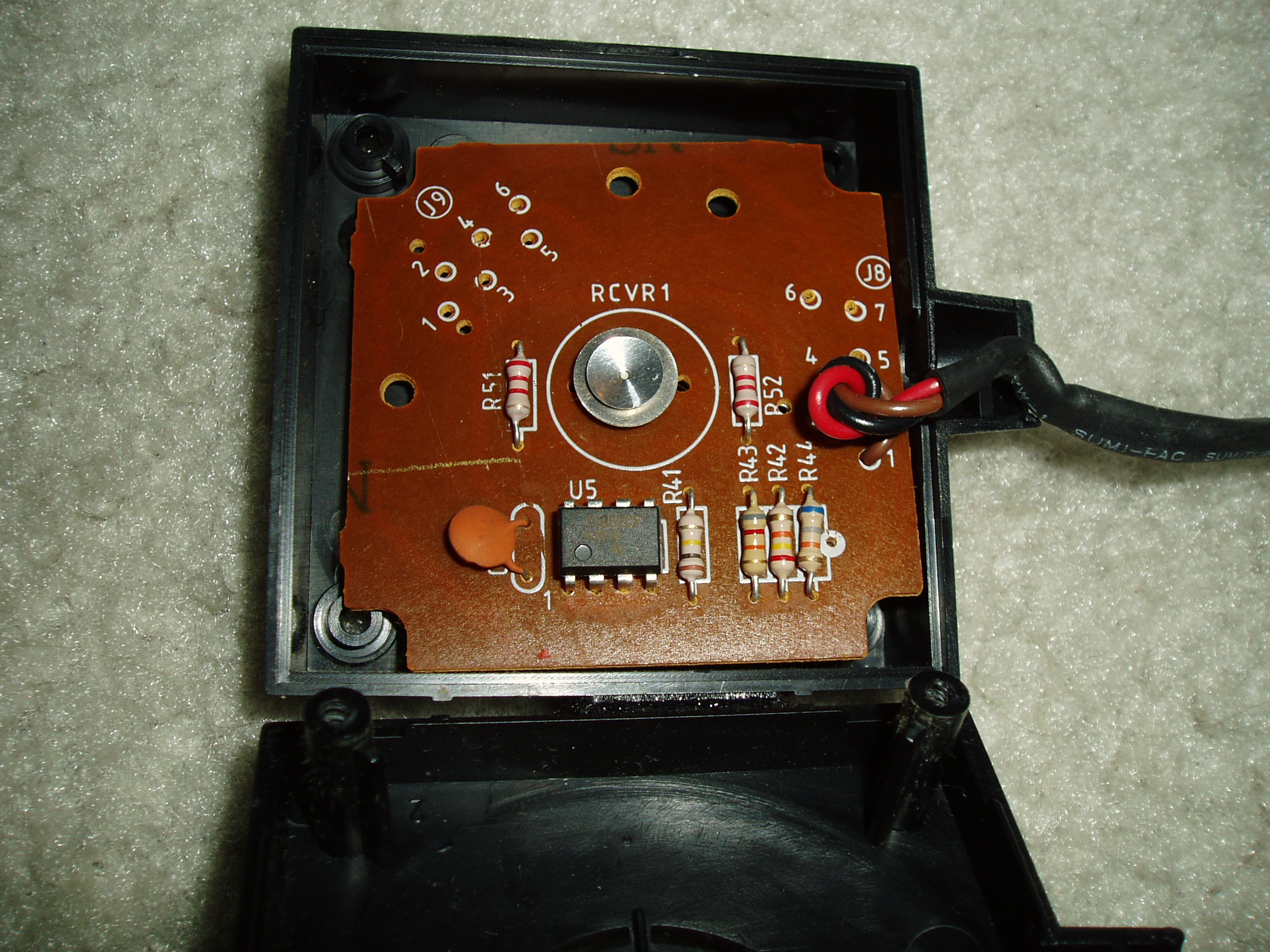
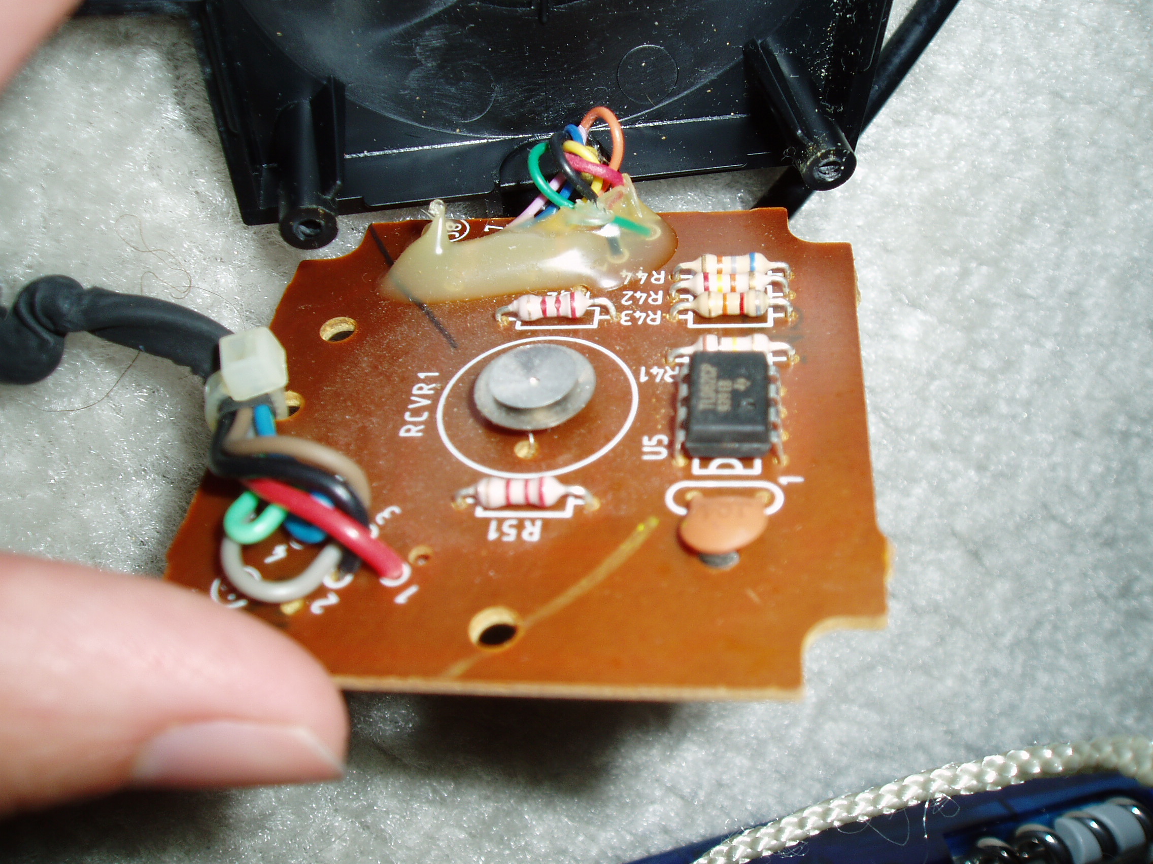
Box 2 has 2 boards- a clone of #1/#3, and the LED board containing a somewhat prominent Texas Instruments / MALAYSIA 8935AS SN74LS164N. Which still doesn't look big enough to be a proper CPU. (EDIT: THIS is a shift-register. Serial-in-parallel-out shift reg, precisely, meaning it's probably taking a bitstream in and using it to drive all the LEDs at once - http://www.datasheetcatalog.com/datashe ... 164N.shtml) http://www.psychsoftware.org/stuff/temp ... 020332.JPG
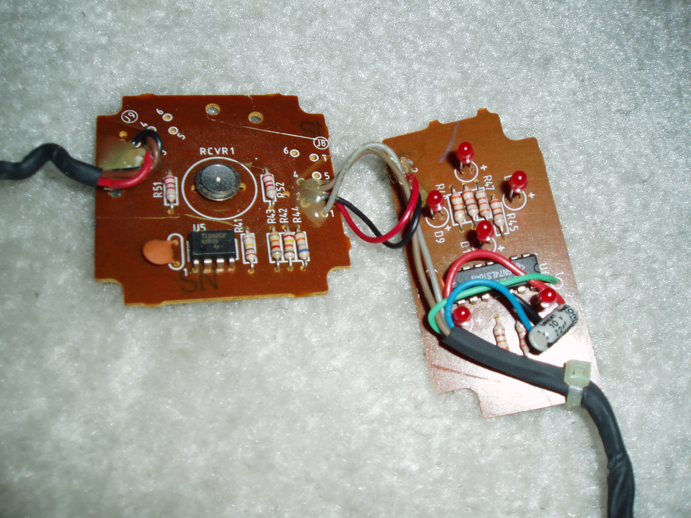
Save copies of the photos if you want them; I'm not going to guarantee perma-hosting, at least not in that location.
There's certainly nothing big enough to be a cop888 in any of those locations. I seem to recall reading somewhere that the brain chip was indeed in the glove, which may mean it is on the backside of the D-pad PCB.
Many thanks for uploading the photos!
Yes, the COP should be 44pin SMD chip on the control-pad board; since it's SMD, one can't see solder pads on the PCB-back-side photo that I've found.
As how I understand the COP pinouts: The microwire feature is used to receive serial data from NES. And in the opposite direction, the 4021 parallel-in serial-out shift register is used to send serial data to NES.
And there's a 8x3 keyboard matrix; 3 outputs, and 8 inputs; ie. the thing outputs a LOW level on one row, and checks if any column inputs go LOW (=button is pressed). The pull-ups are just there to drag the columns HIGH if the button isn't pressed (so there's just logic LOW and HIGH on that pins, no analog stuff).
For the microphones, I'd have expected 3 inputs (though Tim has listed only two pins going to "near receivers") (but I'd guess there might be one more microphone pin somewhere).
The whole NES data, LED data, and MICrophone data is squeezed through the 9pin connector on the junction box: Two pins for VCC and GND, three pins for NES connector, and presumably three pins for the microphones. That would would leave only 1 spare pin. Should be pretty impossible to control the six LEDs through that 1 spare pin...
That's why I was suggesting that 4021 shift-register (and the wires in the cable) are shared for both COP-to-NES and COP-to-LED. So, the 4021's serial-output is wired both to NES, and to the 74LS165's serial-input on the LED board (and the 74LS165's parallel output then wired to the LEDs).
With "Error Flags" I meant you "occlusion" byte, which would be the last byte transferred (If you are doing it the way as Super Glove Ball). So, in analog mode the LED bits should blink between 3Fh (1 frame; no errors) and FFh (2 frames, not ready).
Bit0-3 of that value would be the four "direction-LEDs", bit4-5 would be "start/select" (which have no LEDs), and bit 6-7 would be the two "button LEDs".
So, with the 3Fh/FFh values, the upper four LEDs should glow permanently, and lower two LEDs should flimmer (which may look as they are dimmed to medium brightness). At least, I'd think that it'd look like so in Glove Ball. EDIT: Or more likely vice-versa: FFh=All LEDs OFF, 3Fh=Lower 2 LEDs ON.
During the transfer, all LEDs would blink more or less "randomly" while new data is shifted-in, but that should occur only for very short moments, probably one won't see that at all.
Ah, okay, didn't knew that 3rd OBJ was intended for in your test program. I don't have transfer "timeouts" yet emulated, so packets in my emu doesn't run in sync with the test program - which caused the 3rd OBJ to jump randomly. Sorry for the confusion.
Quote:
For the microphones, I'd have expected 3 inputs (though Tim has listed only two pins going to "near receivers") (but I'd guess there might be one more microphone pin somewhere).
If they're going to the LM324s in the junction box proper, those receiver pins may be the serial send/receive pins for communication with the NES. This also makes sense because the WR# write pin is reported as tying directly to a LM324 pin, while the RD# read pin is reported as tying to likely some Resistor/Capacitor buffer before entering digital world. The COP888 does have direct serial I/O capacity. And in fact, certain write-ups describe that particular series of chips as being pathologically serial, even in the way it reads instructions from its own internal ROM.
I also have some doubts that the designers would have necessarily allocated pins for all 3 mics and 2 speakers in parallel given that they only need one speaker/mic pair at a time. I'd suspect the speakers are in the "from top of glove" pin set (in fact... XMTR is probably [trans]MiTteR). The microphones are a little bit of a puzzle, but one which may be illuminated if we ask why 8 op-amp 'gates' are needed for 2, or at most 3, lines communicating with the NES, particularly when each mic PCB has its own dual op-amp chip. My analog EE is very rusty, but I could see a possibility of them hacking together a primitive multiplexor or delay circuit to serialize the mic returns if there's no obvious parallel pin set on the COP888.
Quote:
The whole NES data, LED data, and MICrophone data is squeezed through the 9pin connector on the junction box: Two pins for VCC and GND, three pins for NES connector, and presumably three pins for the microphones. That would would leave only 1 spare pin. Should be pretty impossible to control the six LEDs through that 1 spare pin...
I have seen no indication that the LEDs are programmer-accessible; read or write. They seem to be automatically operated. But with the serial-to-parallel chip boxed in on the LED PCB, one pin could very easily control all LEDs if the LED state is determined on the microcontroller.
Quote:
With "Error Flags" I meant you "occlusion" byte, which would be the last byte transferred (If you are doing it the way as Super Glove Ball). So, in analog mode the LED bits should blink between 3Fh (1 frame; no errors) and FFh (2 frames, not ready).
Bit0-3 of that value would be the four "direction-LEDs", bit4-5 would be "start/select" (which have no LEDs), and bit 6-7 would be the two "button LEDs".
So, with the 3Fh/FFh values, the upper four LEDs should glow permanently, and lower two LEDs should flimmer (which may look as they are dimmed to medium brightness). At least, I'd think that it'd look like so in Glove Ball. EDIT: Or more likely vice-versa: FFh=All LEDs OFF, 3Fh=Lower 2 LEDs ON.
During the transfer, all LEDs would blink more or less "randomly" while new data is shifted-in, but that should occur only for very short moments, probably one won't see that at all.
If anything, it might make sense if the LEDs reflected every single byte of data output by the glove to the NES, not just one particular "final" field. That's closer to the actual appearance of the LEDs. Very rarely is one lamp ever solidly illuminated in raw mode; I've only ever seen a combination of solid and flicker when I've gotten into really unorthodox configurations with more static garbage fields than dynamic data.
But if the glove's output packets are splitting off to drive the LEDs, that's even more evidence that the output packets are serialized by the time they hit the junction box, as nothing in the junction box or frame would serialize the data prior to the LED serial-to-parallel chip.
Reexamining my photos, it's fairly clear that the wiring through the frame is
Box 1:
- Hot (red)
- Ground (black)
- Mic1 data (brown)
Box2:
- all Box1
+ Mic2 data (gray)
+ LED data+clock (green/blue)
Box3:
- all Box1
- all Box2
+ Mic3 data (mic data likely recolored yellow/orange/pink on exit; not sure which is which without re-opening the box and looking at the trace side)
From there, it would probably be easy enough to look at the traces on the junction PCB to see if blue/green share any connections with the to-NES port or figure out where yellow/orange/pink go. I may try that at some point, but it sounds like you could really stand to get your own glove
Quote:
one pin could very easily control all LEDs if the LED state is determined on the microcontroller.
The shift register (on the LED board) needs Data and Clk (two pins).
Quote:
If anything, it might make sense if the LEDs reflected every single byte of data output by the glove to the NES, not just one particular "final" field.
Yes, exactly. Just what I was saying. But you would barely see them (blinking only for very short moments), so only the final ones (which last for longer time) should be visible.
Quote:
That's closer to the actual appearance of the LEDs. Very rarely is one lamp ever solidly illuminated in raw mode; I've only ever seen a combination of solid and flicker when I've gotten into really unorthodox configurations with more static garbage fields than dynamic data.
What's with the Super Glove Ball game? That should be the normal/official case... I couldn't find any videos or descriptions how it should look like.
But I would stay with my theory: The two button LEDs should be flimmering, the four direction LEDs should be off - unless you cover the speakers/microphones, then some of the direction LEDs should flimmer, too (in respect to the lower 4 occlusion bits).
Quote:
it would probably be easy enough to look at the traces on the junction PCB to see if blue/green share any connections with the to-NES port or figure out where yellow/orange/pink go.
What traces? You've uploaded only component side photos. But, following traces on photos would be a pain anyways (easiest would be using a multimeter to check for 0 ohm connections).
Yeah, having a glove at hand would be nice... and the NES CompuTrainer from RacerMate... and all the other odd NES controllers. But I don't have the money and storage to buy all that stuff.
Well it seems that the power glove does have ring finger control, in addition to thumb, index and middle fingers, but the middle one on mine is broken. (no response, FingersByte bits 2-3 stuck at "10")
It's probably likeky that the flex sensor in these gloves degrades over time or was just fragile. I wonder if it can be repaired.
So what's the verdict on the reads? Has it been determined if the glove can send a full packet of reliable data in less than three NTSC frames?
It's probably likeky that the flex sensor in these gloves degrades over time or was just fragile. I wonder if it can be repaired.
So what's the verdict on the reads? Has it been determined if the glove can send a full packet of reliable data in less than three NTSC frames?
Less than 3 frames? No, I think the latest info was 4 frames, and sometimes 3 frames (see http://nesdev.com/bbs/viewtopi ... 2301#92301) the only later news was that there is the "ready byte", if you are polling it once per frame then you should get the possible rate, without getting into unstable situations. If 3 or 4 frames is too slow for your purposes - you could try to poll it more than once per frame; and maybe receive data every 2.5 or 3.5 frames.
No idea if it's possible to repair the flex sensors, how they do look like, and if one can buy replacement parts. Is it difficult to disassemble them?
If they are actually broken then you are probably in trouble - soldering would probably melt them, and conductive silver would probably break as soon as you flex the fingers. If you are lucky, then it's just a dirty contact between the wire & sensor.
I don't have a Power Glove, but was reading about it today, and found the technical information in this thread very interesting.
One additional thing I'm interested in is if it's possible to manually enter advanced programs on the glove's keypad.
In the Power Glove manual, the Problems and Solutions (page 34) says (emphasis mine):
This makes it sound like advanced programs could be manually entered on the glove keypad.
I think it is unusual the glove requires you to press ENTER twice to load a program. Wouldn't one ENTER press suffice? I suspect there's a hidden reason two ENTER presses are required. Perhaps you are able to enter advanced programming steps after the first ENTER press and the second ENTER press finally ends the programming mode.
Perhaps someone with a Power Glove would be interested in testing if undocumented key sequences in the programming mode have any effect...
One additional thing I'm interested in is if it's possible to manually enter advanced programs on the glove's keypad.
In the Power Glove manual, the Problems and Solutions (page 34) says (emphasis mine):
Quote:
P: I would like to use different motions with the game I am playing.
S: The glove comes with 14 different programs, each with different moves. [...] Special games like Bad Street Brawler have more programs on them. There will also be special "editing" codes published in magazines for more games.
S: The glove comes with 14 different programs, each with different moves. [...] Special games like Bad Street Brawler have more programs on them. There will also be special "editing" codes published in magazines for more games.
This makes it sound like advanced programs could be manually entered on the glove keypad.
I think it is unusual the glove requires you to press ENTER twice to load a program. Wouldn't one ENTER press suffice? I suspect there's a hidden reason two ENTER presses are required. Perhaps you are able to enter advanced programming steps after the first ENTER press and the second ENTER press finally ends the programming mode.
Perhaps someone with a Power Glove would be interested in testing if undocumented key sequences in the programming mode have any effect...
Yeah... I haven't done much with the PowerGlove recently from a research standpoint, although there will be a new release of Nesglovphone with one or two new features as soon as I get around to doing a demo recording. These days, if anything, my focus is shifting to Virtual Boy ( http://www.planetvb.com/content/downloa ... stsvb.html ), but that's a discussion for another thread.
But so far as I remember, the bottleneck is not so much on sending the data- you can poll it to your heart's content just like any input device- the glove's internals simply can't build new packets instantaneously, so if you ask it to put a lit of data in the packet, you need to give it sufficient time to get ready. If you want it to be ready faster, ask for fewer data fields. I have no recollection of how/whether there was a "ready" byte and I'm too lazy to review the whole thread, but it would make a lot of sense if one does exist, and if so, yes, the process would be along the lines of: read header/ready byte -> check "ready" state -> if ready, read more (data packet) bytes.
I could conceive of alternate explanations for needing to press Enter twice to change programs- early digital state machine systems were not always the prettiest hacks- but the notion of user-programmability is intriguing. There is, with certainty, some small microcontroller in the glove, and my experiments with initialization codes seemed to suggest that there were swaths of data in there not necessarily related to normal intended operation. The riddle which may never be answered is whether the raw data "modes" I discovered were intentional-but-not-yet-documented, or simply artifacts of deterministic program/junk data that was never intended to be indexed into. That might help clear up whether "programming" modes via the keypad were a fully flexible specification system, or just a hypothetical back-door to get at similar deterministic alternate behavior that wouldn't be worth documenting until someone wanted/needed it.
As to repair, I now have 2 Gloves (the one that came with my full setup, and a second which, in isolation, had likely long since been relegated to a costume prop), but I'm still not brave enough to do a teardown until one fails so absolutely that I can't use it for anything else. The sensors are some manner of thin sheet laminated into the rubber fingers of the glove, so repairing/replacing them would be impossible without destroying the glove as-such (which is not to say that after surgery, you might not find another fabric glove to bond the electronics back onto). The access screws for the rectangular block on the glove (the "gamepad"/keyboard) are accessible enough, but that's not where the flex sensor leads likely originate, and the screws to get into the oblong emitter nodule (assuming it's not just glued together) are on the far side of the glove fabric. I'm pretty sure I've seen a few pics of both sets of internals, but didn't glean any earth-shakingly useful information from them at the time.
Seems to me the boys that played with VR and attaching the PowerGlove to the PC par. port would have figured out the mysteries. I wonder if any good FAQs still exist from those days..
BIG AND I MEAN HUGE NEWS
When poking around for resources on the Miracle Piano, I stumbled across the website of Paul White, one of the retired original engineers on the Miracle and Power Glove. After striking up a conversation, he was willing to share the recollections and resources he had accumulated.
Of course, that isn't too new. What is new and merits a big, long,
drumrollllllllllllllllll....
Yes, to all initial indications, this is THE SOURCE TO THE EXECUTABLE CODE EMBEDDED ON THE ONBOARD PROCESSOR OF THE POWER GLOVE. I say "to all initial indications" because I don't have time right now to fully investigate, but the source and comments look believable, and if it is, this is huge and ought to crack the whole apparatus wide open to proper emulation.
* editorial note: being in software development myself, I could easily see how this might be an earlier or later version than actually ended up on the Glove if it's just the copy that Paul dropped on a floppy for his own collection. Still, it's NaN% more than I think we've ever had to work with, and odds are since he did the actual coding and had his hands on the source most readily, even if it isn't the shipped build, it's pretty darn close and ought to at least be concretely testable against actual Glove behavior.
When poking around for resources on the Miracle Piano, I stumbled across the website of Paul White, one of the retired original engineers on the Miracle and Power Glove. After striking up a conversation, he was willing to share the recollections and resources he had accumulated.
Quote:
The power glove used a special control script to convert various gestures into Nintendo button presses. I think you would punch in the appropriate code on the PG keypad to select the gesture template for the game you wanted to play. The PG to Nintendo interface was simple, like a button controller, so standard games would work without modification. As I see you know, there was also the raw mode, where special software on the Nintendo side could read the various glove parameters directly.
Of course, that isn't too new. What is new and merits a big, long,
drumrollllllllllllllllll....
Quote:
I found some nice Power Glove information for you. The source code and
various utilities are available here:
[attached to post]
The PG uses a National Semiconductor COP888 microcontroller.
You may be able to find info about the assembly language syntax on the
web. If not, I may still have some data books around somewhere.
I haven't tried running the NGL.EXE program, but I seem to recall it has
something to do with generating gesture templates, or some such.
Quote:
ASM888.EXE COP888 assembler
HEXLM.EXE Hex to Load Module utility
LMHEX.EXE Load Module to Hex utility
NGL.EXE Nintendo Glove Language utility ?
PG.MAC Main Power Glove source
PGCON.INC Power Glove constants
PGMEM.INC Power Glove memory definitions
PGTEMPL.INC Power Glove template include file
COP888.INC COP888 header file
HEXLM.EXE Hex to Load Module utility
LMHEX.EXE Load Module to Hex utility
NGL.EXE Nintendo Glove Language utility ?
PG.MAC Main Power Glove source
PGCON.INC Power Glove constants
PGMEM.INC Power Glove memory definitions
PGTEMPL.INC Power Glove template include file
COP888.INC COP888 header file
Quote:
Most of the assembly code is pretty straightforward reading, with the possible exception of the "X" command. As I recall, the COP processor doesn't have a STORE command as such, but it does have an eXchange command that swaps the accumulator with the specified memory location.
Unfortunately I don't have copies of the PG schematic, because it wasn't created on my computer. I think I must have worked from a printed copy, which I no longer have. There are references in the code to some "high voltage" stuff. There was an output pin connected to an inductor/diode/capacitor circuit, and it had to be pulsed periodically to generate a high voltage for the piezoelectric ultrasonic beepers. They needed a fairly high voltage to get loud enough to provide a reasonable range. You can probably figure out the rest.
Unfortunately I don't have copies of the PG schematic, because it wasn't created on my computer. I think I must have worked from a printed copy, which I no longer have. There are references in the code to some "high voltage" stuff. There was an output pin connected to an inductor/diode/capacitor circuit, and it had to be pulsed periodically to generate a high voltage for the piezoelectric ultrasonic beepers. They needed a fairly high voltage to get loud enough to provide a reasonable range. You can probably figure out the rest.
Yes, to all initial indications, this is THE SOURCE TO THE EXECUTABLE CODE EMBEDDED ON THE ONBOARD PROCESSOR OF THE POWER GLOVE. I say "to all initial indications" because I don't have time right now to fully investigate, but the source and comments look believable, and if it is, this is huge and ought to crack the whole apparatus wide open to proper emulation.
* editorial note: being in software development myself, I could easily see how this might be an earlier or later version than actually ended up on the Glove if it's just the copy that Paul dropped on a floppy for his own collection. Still, it's NaN% more than I think we've ever had to work with, and odds are since he did the actual coding and had his hands on the source most readily, even if it isn't the shipped build, it's pretty darn close and ought to at least be concretely testable against actual Glove behavior.
...and of course BATCAVE is the re-entry point to BATLOOP. Makes perfect sense. And ye gods this is well-commented.
I have not experienced this much happy while reading ASM since digesting the Virtual Boy sacred scrolls
I have not experienced this much happy while reading ASM since digesting the Virtual Boy sacred scrolls
PG.MAC wrote:
; Set up upload pointers
;
BT:
LD A,[B]
RLC A ; Locate bitmap of upload values in template
AND A,#01E ; mask all but gesture byte count
INC A ; Add 2 for template header and logic byte
INC A ; count
ADD A,#TEMPLATE
X A,B
LD A,[B+] ; Save bitmap in GSTAT
X A,GSTAT1
LD A,[B+]
X A,GSTAT2 ;
; Build list of data addresses following logic in template
LD A,B ; RAM address in B is transferred to X
PUSH A
X A,X ;
POP A
X A,GBASE ; Save pointer for upload routine to use
LD CREG,#0 ; Initialize bit counter
BATLOOP:
LD A,CREG
JSR GBX ; Get B pointer to GSTAT1 or 2 and A=bitmask
AND A,[B]
IFNE A,#0
JP PUTONE
BATCAVE:
JSR INCREG ; Increment CREG
IFNE A,#15 ; (value of CREG before incrementing) = 15 ?
JP BATLOOP
LD A,#0FF
X A,[X] ; Put FF marker at end of list
JMP ZSTAT
PUTONE: ; Put a pointer in the table
LD A,CREG
ADD A,#L(IATABLE)
LAID
X A,[X+]
JP BATCAVE
Pretty cool! The tools run fine in DOSBox.
Previously:
I immediately looked over the source code when it was posted, and it does suggest some editing abilities are available from the Power Glove's keypad. I had wanted to re-examine the code to make sure I didn't make any mistakes, but I haven't had time. For now, here are some notes from when I last looked at it (September 2014).
In the descriptions below, n is a decimal digit, and x, y, and z are hexadecimal digits. [ ]* means you can press the enclosed sequence 0 or more times. To enter hexadecimal digits, use the following buttons:
digit: A B C D E F
button: A B Left Up Down Right
Press Prog to enter the program mode. In the program mode, you can press:
You can press Prog to clear the last digit (or byte? need to check the code again to confirm).
You can chain load and edit commands one after another. After your last command, press Enter a second time to exit the program mode.
Also, you can press Prog Prog Prog to reset all. (That is, press Prog to enter programming mode, then Prog Prog to reset all.)
I may have made some mistakes interpreting the code. And we aren't sure if the code is the same as used on production units.
- The Power Glove manual mentions "special editing codes", maybe pressing something between the first and second Enter press would do something?
- The source code for the Power Glove onboard processor executable code
I immediately looked over the source code when it was posted, and it does suggest some editing abilities are available from the Power Glove's keypad. I had wanted to re-examine the code to make sure I didn't make any mistakes, but I haven't had time. For now, here are some notes from when I last looked at it (September 2014).
In the descriptions below, n is a decimal digit, and x, y, and z are hexadecimal digits. [ ]* means you can press the enclosed sequence 0 or more times. To enter hexadecimal digits, use the following buttons:
digit: A B C D E F
button: A B Left Up Down Right
Press Prog to enter the program mode. In the program mode, you can press:
n Enter
Load template n.
n n Enter
Load template nn.
A x Enter y y [z z]* Enter
Insert a gap of x bytes starting at offset yy in the template definition bytes, then begin overwriting with bytes zz.
B x Enter y y [z z]* Enter
Delete x bytes starting at offset yy in the template definition bytes, then begin overwriting with bytes zz.
You can press Prog to clear the last digit (or byte? need to check the code again to confirm).
You can chain load and edit commands one after another. After your last command, press Enter a second time to exit the program mode.
Also, you can press Prog Prog Prog to reset all. (That is, press Prog to enter programming mode, then Prog Prog to reset all.)
I may have made some mistakes interpreting the code. And we aren't sure if the code is the same as used on production units.
A new potential side project led me back to my old PG notes, they in turn led me more properly into the PG.MAC source code, and while I didn't find answers to the raw-mode questions I had, I did conclusively find the section related to parsing the input stream for custom joypad processing. Nocash got remarkably close in his analysis; I can only really provide confirmation.
Omitting the very first header byte, packet length, which (perhaps naturally) does not appear to be part of the TEMPLATE data proper, the structure does appear to be a header byte preceding N 16-bit gesture definitions, followed by a second header byte and N 8-bit gesture-logic statements.
Specifically,
Line 2041 of PG.MAC begins what is likely the parsing section for what were previously termed the “16-bit opcodes”, referring to a “gesture header byte” and a “gesture data byte”
I am assuming TEMPLATE is the address of the start of the received message structure.
First, an initial gesture address GADDR is computed (1 byte after TEMPLATE) and cached.
Then, the contents of address TEMPLATE are loaded, masked with 0x0F, and interpreted as the count of gestures to follow; consistent with earlier reverse-engineering of the “16-bit Block Header.”
If >0, this count is stored in NYREG and gesture loop counter GNUM is initialized to 1.
Looping over an incrementing GADDR, 2 bytes are read (cached by address) for each gesture entry:
The first byte is a header and gets masked by 0x3F prior to processing. It would appear this mask is used to ignore “last state” and “1-shot” flag bits.
The second byte is a data byte; cached in X.
If the entire gesture header (after the 3F mask) is 0x00, this is a noop (“A gesture type of 00 would be flex with no fingers set in the bitmap”).
otherwise, the header byte is masked with 0x03 and is identified as one of
00b = flex-only
01b = position
10b = orientation
11b = “D. POSITION” (unknown term)
Values of 0 and 2 (00b and 10b) are explicitly tested to jump to respective GFLEX and GORIENT subroutines; 1 and 3 (01b and 11b) fall through, caching some convenience variables before entering the position subroutine GPOSITION.
GPOSITION interprets the cached X data byte as a “vector” lookup. It RLCs the value (presumably arithmetic rotate-left with carry) to double it, then masks it with 0x06, apparently to isolate vales (in the 2 masked-in bits) of
00b = X-axis
01b = Y-axis
10b = Z-axis
11b = don’t-care
before adding the masked value to a base address, using the resulting address (by storing it in B and then loading from the addresses contained in “B+” (postincrement) and B) to look up what appears to be the current and old position vectors (on that axis?)
Flow then JSRs into GADB, with a comment indicating that the data pointer in B is to the gesture header byte (presumably upon return, as it is not so going in).
The header (data at address B) is bit-tested (REL = bit 2, according to PGCON.INC) to determine if an absolute or relative gesture is being specified; relative jumps to subroutine RELATIVE, absolute falls through.
ABSOLUTE evaluation logic appears, in a nutshell, to:
- check whether the gesture data byte is direction-consistent with the current ongoing direction vector (CURR) sign, aborting/resetting detection otherwise
- take the absolute value of the current vector (CURR)
- shift-mask the data byte (X) down to 6 bits even: 2 arithmetic right rotations followed by a mask with 0x3E, retaining 2 of the top 4 and 3 of the bottom 4 bits
- test/return if the processed data value is greater than the CURR ongoing gesture vector
subsequent comments/subroutines indicate that only the largest single-axis (x/y/z) gesture so-detected will return as true/triggered, and only if it was previously false.
RELATIVE evaluation logic is trickier, and appears to
- look up a “turning point” (cached in TURN) by first masking the data byte (X) by 0x03 to get an axis code (as before) then adding that to TURNX (presumably a table address), and reading the data in the resultant address (via B)
- subtract the TURN point from the CURR current vector (cacheing the result in CMT)
- GADB-lookup the header and shift-mask it into a “RESET” value: 1 arithmetic right rotate, mask with 0x1C to “Keep 5 bit magnitude, 3 bit resolution” and cache it in CREG. So apparently the original header was a 2-bit requested data type and a 3-bit reset value of still-ambiguous function.
- perform a sophisticated walk down a table of tristate gesture component definitions, continuing to track the gesture I believe so long as the current gesture is positively matched (PTRUE) and the next gesture is not yet evaluated (RFALSE) as opposed to definitively nonmatched (NTRUE); PTRUE and NTRUE being determined by +/- difference from SET (X data value, processed to 6-bit similarly to before)
- reset the turn point for detection if the current vector (C===CURR) and turn point (T===CMT===CURR-TURN) both exceed the last vector(?); fail if the difference between the current vector and turn point exceeds the reset threshold CREG as previously computed. Meaning the original header was a 2-bit requested data type and a 3-bit reset sensitivity, or to borrow the format of subsequent comments:
Finger gesture processing is probably best summarized by the big comment
indicating a system of looking for “bitmap” levels on either 1 or 2 fingers and returning an AND match
likewise with orientation
which match nocash’s analysis rather precisely.
The only mystery is whether the single 0x0800 entry present in the gesture block of the “raw mode” packet is anything more significant than a vacuous middle finger.
Parsing then proceeds to a “Gesture logic” (line 2499) statement parser/processor which begins with a check of bit 7 of (presumably) what we’ve been calling the 8-bit section header, aborting back to the main loop if true (meaning the “extra 6 bytes” nocash observed are doubly confusing…)
From here (line 2506), things begin to get crazy, appearing (as nocash surmised) to be a whole metalanguage of “logic statements,” “indent states,” truth tables, processes, etc., implemented in assembly, to act on bytecode, all for the purpose of chaining the defined gestures (16-bit opcodes) into evaluation sequences to yield true/false button states.
The 8-bit opcodes appear to reduce to control codes in the low 3 bits of the high nybble as defined
Those 8 control codes jump to handlers with header comments as follows:
LTMPN
editorial note: “template” appears to be the internal term for a set of gestures + logic, or in our nomenclature, 16-bit + 8-bit opcodes
LIFG
LTIFG
LEIFG
LANDG
LORG
LENDIF
LESLEDO
For standard statements (high nybble 0-7), the low nybble is parsed by the EVAL subroutine, which farms the actual parsing off down another rabbit hole, but it looks like it contains a 1-based (1-16 range) index for the 16-bit gesture entry to operate on. Actual parsing process is
- load the byte into A
- mask in the low nybble (by AND with 0x0F)
- subtract 1
- load into B the address of either a (presumably) gesture evaluation state array (GSTAT1) if A<=7 or status flags (GSTAT2) if A>7
- mask down to the low 3 bits (AND 0x07)
- use headache-inducing indirect lookup magic to compute 2^A and store it back in A
- use A as a mask into the data at B (AND A,[B]) and return whether that result is true (0xFF) or false (0x0)
A value of 0 in the low nybble appears to just set a flag to trigger a beep.
A value of 8 or higher in the high nybble indicates THEN (0x8_-0xB_) or ELSE (0xC_+) commands, which appear at first glance to conditionally increment the “indent” level and proceed based on the truthiness of the previous statement or decrement the “indent” level and update the current truthiness consistent with prior and current level results. They also both flow through to a further DoAction handler which calls out that 0xB_ or 0xF_ statements invert the referenced gesture. Subsequent lines seem to indicate this is an inversion of the gesture’s result status or corresponding output bit/byte.
The low nybble, if nonzero, triggers actions based on previously defined gestures.
If >0x08, special handling (DoSpecial) is invoked. This turns out to be another straightforward jump table:
for noop (EndAct), conditionally resetting everything if it hasn’t been done before (CTR1CE), centering All/X/Y/Z axes (Cent*), or resetting the flex, center-once and beep flags (ResAct).
Otherwise, the corresponding button-bit of the NES joypad is selected (modulo a swap flag which can cause A and B (0x07 and 0x08) to be swapped) and cached on the stack. The original instruction’s bits masked by 0x30 are then checked to see if the action being defined should be “pulsed 2” (0x20), “pulsed 1” (0x10) or continuous (0x0). I.e., out of the original high nybble, which by now we have determined to be on the 0x8_-0xF_ range, the codes 0x8_ and 0xC_ are continuous actions, 0x9_ and 0xD_ are “pulsed 1”, and 0xA_ and 0xE_ are “pulsed 2”. The remaining 0xB_ and 0xF_ were covered earlier in the inversion clause.
So basically, again in a representation akin to other source comments,
If EXT is 0 then STATEMENT is a basic control command, and based on OPSET, the command is evaluated with the current value of either the gesture (OPSET=0) or status flag (OPSET=1) indexed by OPERAND.
if EXT is 1 then STATEMENT is an action command as
000b = THEN continuous trigger
001b = THEN 1-pulse trigger
010b = THEN 2-pulse trigger
011b = THEN inverted trigger
100b = ELSE continuous trigger
101b = ELSE 1-pulse trigger
110b = ELSE 2-pulse trigger
111b = ELSE inverted trigger
For further help interpreting, it may be useful to consult a COP888 datasheet. I found one at http://www.engineering.uiowa.edu/sites/ ... 010830.pdf
Omitting the very first header byte, packet length, which (perhaps naturally) does not appear to be part of the TEMPLATE data proper, the structure does appear to be a header byte preceding N 16-bit gesture definitions, followed by a second header byte and N 8-bit gesture-logic statements.
Specifically,
Line 2041 of PG.MAC begins what is likely the parsing section for what were previously termed the “16-bit opcodes”, referring to a “gesture header byte” and a “gesture data byte”
I am assuming TEMPLATE is the address of the start of the received message structure.
First, an initial gesture address GADDR is computed (1 byte after TEMPLATE) and cached.
Then, the contents of address TEMPLATE are loaded, masked with 0x0F, and interpreted as the count of gestures to follow; consistent with earlier reverse-engineering of the “16-bit Block Header.”
If >0, this count is stored in NYREG and gesture loop counter GNUM is initialized to 1.
Looping over an incrementing GADDR, 2 bytes are read (cached by address) for each gesture entry:
The first byte is a header and gets masked by 0x3F prior to processing. It would appear this mask is used to ignore “last state” and “1-shot” flag bits.
The second byte is a data byte; cached in X.
If the entire gesture header (after the 3F mask) is 0x00, this is a noop (“A gesture type of 00 would be flex with no fingers set in the bitmap”).
otherwise, the header byte is masked with 0x03 and is identified as one of
00b = flex-only
01b = position
10b = orientation
11b = “D. POSITION” (unknown term)
Values of 0 and 2 (00b and 10b) are explicitly tested to jump to respective GFLEX and GORIENT subroutines; 1 and 3 (01b and 11b) fall through, caching some convenience variables before entering the position subroutine GPOSITION.
GPOSITION interprets the cached X data byte as a “vector” lookup. It RLCs the value (presumably arithmetic rotate-left with carry) to double it, then masks it with 0x06, apparently to isolate vales (in the 2 masked-in bits) of
00b = X-axis
01b = Y-axis
10b = Z-axis
11b = don’t-care
before adding the masked value to a base address, using the resulting address (by storing it in B and then loading from the addresses contained in “B+” (postincrement) and B) to look up what appears to be the current and old position vectors (on that axis?)
Flow then JSRs into GADB, with a comment indicating that the data pointer in B is to the gesture header byte (presumably upon return, as it is not so going in).
The header (data at address B) is bit-tested (REL = bit 2, according to PGCON.INC) to determine if an absolute or relative gesture is being specified; relative jumps to subroutine RELATIVE, absolute falls through.
ABSOLUTE evaluation logic appears, in a nutshell, to:
- check whether the gesture data byte is direction-consistent with the current ongoing direction vector (CURR) sign, aborting/resetting detection otherwise
- take the absolute value of the current vector (CURR)
- shift-mask the data byte (X) down to 6 bits even: 2 arithmetic right rotations followed by a mask with 0x3E, retaining 2 of the top 4 and 3 of the bottom 4 bits
- test/return if the processed data value is greater than the CURR ongoing gesture vector
subsequent comments/subroutines indicate that only the largest single-axis (x/y/z) gesture so-detected will return as true/triggered, and only if it was previously false.
RELATIVE evaluation logic is trickier, and appears to
- look up a “turning point” (cached in TURN) by first masking the data byte (X) by 0x03 to get an axis code (as before) then adding that to TURNX (presumably a table address), and reading the data in the resultant address (via B)
- subtract the TURN point from the CURR current vector (cacheing the result in CMT)
- GADB-lookup the header and shift-mask it into a “RESET” value: 1 arithmetic right rotate, mask with 0x1C to “Keep 5 bit magnitude, 3 bit resolution” and cache it in CREG. So apparently the original header was a 2-bit requested data type and a 3-bit reset value of still-ambiguous function.
- perform a sophisticated walk down a table of tristate gesture component definitions, continuing to track the gesture I believe so long as the current gesture is positively matched (PTRUE) and the next gesture is not yet evaluated (RFALSE) as opposed to definitively nonmatched (NTRUE); PTRUE and NTRUE being determined by +/- difference from SET (X data value, processed to 6-bit similarly to before)
- reset the turn point for detection if the current vector (C===CURR) and turn point (T===CMT===CURR-TURN) both exceed the last vector(?); fail if the difference between the current vector and turn point exceeds the reset threshold CREG as previously computed. Meaning the original header was a 2-bit requested data type and a 3-bit reset sensitivity, or to borrow the format of subsequent comments:
Code:
;
; Motion gesture Header byte:
; Last /1 shot / RESET (3) /RELATIVE (1) / 0 / 1 ;
;
; Data byte:
; SET (5) / DIRECTION / AXIS (2) /
;
; Motion gesture Header byte:
; Last /1 shot / RESET (3) /RELATIVE (1) / 0 / 1 ;
;
; Data byte:
; SET (5) / DIRECTION / AXIS (2) /
;
Finger gesture processing is probably best summarized by the big comment
Code:
;
; Flex gesture Header byte:
; <-- second finger <-- first finger <--
; Last /1 shot /THUMB /INDEX /MIDDLE /RING / 0 / 0 ;
;
; Data byte - Set bitmap: 2nd finger / first finger
; 3 / 2 / 1 / 0 / 3 / 2 / 1 / 0 /
;
; Finger map specifies 1 or 2 fingers. If both are true,
; gesture becomes true. If either are false, gesture becomes false.
indicating a system of looking for “bitmap” levels on either 1 or 2 fingers and returning an AND match
likewise with orientation
Code:
; Orientation gesture Header byte:
;
; Last /1 shot / / / / / 1 / 0 ;
;
; Data byte:
;
; End position / Start position ;
;
;
; Last /1 shot / / / / / 1 / 0 ;
;
; Data byte:
;
; End position / Start position ;
;
which match nocash’s analysis rather precisely.
The only mystery is whether the single 0x0800 entry present in the gesture block of the “raw mode” packet is anything more significant than a vacuous middle finger.
Parsing then proceeds to a “Gesture logic” (line 2499) statement parser/processor which begins with a check of bit 7 of (presumably) what we’ve been calling the 8-bit section header, aborting back to the main loop if true (meaning the “extra 6 bytes” nocash observed are doubly confusing…)
From here (line 2506), things begin to get crazy, appearing (as nocash surmised) to be a whole metalanguage of “logic statements,” “indent states,” truth tables, processes, etc., implemented in assembly, to act on bytecode, all for the purpose of chaining the defined gestures (16-bit opcodes) into evaluation sequences to yield true/false button states.
The 8-bit opcodes appear to reduce to control codes in the low 3 bits of the high nybble as defined
Code:
LOGJMP: ; Logic statement jump table
.BYTE L(LTMPN) ; 0
.BYTE L(LIFG) ; 1
.BYTE L(LTIFG) ; 2
.BYTE L(LEIFG) ; 3
.BYTE L(LANDG) ; 4
.BYTE L(LORG) ; 5
.BYTE L(LENDIF) ; 6
.BYTE L(LELSEDO) ; 7
.BYTE L(LTMPN) ; 0
.BYTE L(LIFG) ; 1
.BYTE L(LTIFG) ; 2
.BYTE L(LEIFG) ; 3
.BYTE L(LANDG) ; 4
.BYTE L(LORG) ; 5
.BYTE L(LENDIF) ; 6
.BYTE L(LELSEDO) ; 7
Those 8 control codes jump to handlers with header comments as follows:
LTMPN
Code:
; Load template N now, then restart.
editorial note: “template” appears to be the internal term for a set of gestures + logic, or in our nomenclature, 16-bit + 8-bit opcodes
LIFG
Code:
;
; "IF (G)"
; evaluates the state of gesture G and sets the state
; of the current indent level accordingly if the state of the
; previous indent level is true.
;
; "IF (G)"
; evaluates the state of gesture G and sets the state
; of the current indent level accordingly if the state of the
; previous indent level is true.
;
LTIFG
Code:
;
; "THEN IF (G)"
; increments the indent level if the indent flag
; is clear and then performs an IF (G)
;
; "THEN IF (G)"
; increments the indent level if the indent flag
; is clear and then performs an IF (G)
;
LEIFG
Code:
;
; "ELSE IF (G)"
; decrements the indent level and clears the indent flag.
;
; "ELSE IF (G)"
; decrements the indent level and clears the indent flag.
;
LANDG
Code:
;
; "AND (G)"
; evaluate the state of gesture G and perform a logical
; AND with the state of the current indent level
;
; "AND (G)"
; evaluate the state of gesture G and perform a logical
; AND with the state of the current indent level
;
LORG
Code:
;
; "OR (G)"
; evaluate the state of gesture G and perform a logical
; OR with the state of the current indent level
;
; "OR (G)"
; evaluate the state of gesture G and perform a logical
; OR with the state of the current indent level
;
LENDIF
Code:
;
; "ENDIF"
; decrements the indent level
;
; "ENDIF"
; decrements the indent level
;
LESLEDO
Code:
;
; "ELSE DO"
; pre-decrement the indent level, set current state,
; post-increment the level and set the indent flag.
;
; "ELSE DO"
; pre-decrement the indent level, set current state,
; post-increment the level and set the indent flag.
;
For standard statements (high nybble 0-7), the low nybble is parsed by the EVAL subroutine, which farms the actual parsing off down another rabbit hole, but it looks like it contains a 1-based (1-16 range) index for the 16-bit gesture entry to operate on. Actual parsing process is
- load the byte into A
- mask in the low nybble (by AND with 0x0F)
- subtract 1
- load into B the address of either a (presumably) gesture evaluation state array (GSTAT1) if A<=7 or status flags (GSTAT2) if A>7
- mask down to the low 3 bits (AND 0x07)
- use headache-inducing indirect lookup magic to compute 2^A and store it back in A
- use A as a mask into the data at B (AND A,[B]) and return whether that result is true (0xFF) or false (0x0)
A value of 0 in the low nybble appears to just set a flag to trigger a beep.
A value of 8 or higher in the high nybble indicates THEN (0x8_-0xB_) or ELSE (0xC_+) commands, which appear at first glance to conditionally increment the “indent” level and proceed based on the truthiness of the previous statement or decrement the “indent” level and update the current truthiness consistent with prior and current level results. They also both flow through to a further DoAction handler which calls out that 0xB_ or 0xF_ statements invert the referenced gesture. Subsequent lines seem to indicate this is an inversion of the gesture’s result status or corresponding output bit/byte.
The low nybble, if nonzero, triggers actions based on previously defined gestures.
If >0x08, special handling (DoSpecial) is invoked. This turns out to be another straightforward jump table:
Code:
SPECJP: ; Jump table for special actions
.BYTE L(EndAction) ; 9
.BYTE L(CTR1CE) ; 10
.BYTE L(CentAll) ; 11
.BYTE L(CentX) ; 12
.BYTE L(CentY) ; 13
.BYTE L(CentZ) ; 14
.BYTE L(ResAct) ; 15
.BYTE L(EndAction) ; 9
.BYTE L(CTR1CE) ; 10
.BYTE L(CentAll) ; 11
.BYTE L(CentX) ; 12
.BYTE L(CentY) ; 13
.BYTE L(CentZ) ; 14
.BYTE L(ResAct) ; 15
for noop (EndAct), conditionally resetting everything if it hasn’t been done before (CTR1CE), centering All/X/Y/Z axes (Cent*), or resetting the flex, center-once and beep flags (ResAct).
Otherwise, the corresponding button-bit of the NES joypad is selected (modulo a swap flag which can cause A and B (0x07 and 0x08) to be swapped) and cached on the stack. The original instruction’s bits masked by 0x30 are then checked to see if the action being defined should be “pulsed 2” (0x20), “pulsed 1” (0x10) or continuous (0x0). I.e., out of the original high nybble, which by now we have determined to be on the 0x8_-0xF_ range, the codes 0x8_ and 0xC_ are continuous actions, 0x9_ and 0xD_ are “pulsed 1”, and 0xA_ and 0xE_ are “pulsed 2”. The remaining 0xB_ and 0xF_ were covered earlier in the inversion clause.
So basically, again in a representation akin to other source comments,
Code:
;
; Logic Statement
; EXT / STATEMENT (3) / OPSET / OPERAND (3) /
;
; Logic Statement
; EXT / STATEMENT (3) / OPSET / OPERAND (3) /
;
If EXT is 0 then STATEMENT is a basic control command, and based on OPSET, the command is evaluated with the current value of either the gesture (OPSET=0) or status flag (OPSET=1) indexed by OPERAND.
if EXT is 1 then STATEMENT is an action command as
000b = THEN continuous trigger
001b = THEN 1-pulse trigger
010b = THEN 2-pulse trigger
011b = THEN inverted trigger
100b = ELSE continuous trigger
101b = ELSE 1-pulse trigger
110b = ELSE 2-pulse trigger
111b = ELSE inverted trigger
For further help interpreting, it may be useful to consult a COP888 datasheet. I found one at http://www.engineering.uiowa.edu/sites/ ... 010830.pdf
LoneKiltedNinja wrote:
01b = position [...]
11b = “D. POSITION” (unknown term)
11b = “D. POSITION” (unknown term)
It stands for "dominant position". Both 01 and 11 are handled by the same flow. The bit that is different between them is checked later on:
Code:
SetPosition:
JSR GADB
IFBIT 1,[B] ; Is this a vector dominant gesture ?
JP VDTYPE ; (absolute only) (??)
JP NG6
; Vector dominant position:
; Gesture can only BECOME true if the vector is the largest
; of the three vectors (X, Y, Z), AND the gesture is currently false.
; If vector is NOT dominant, it will not become true.
;
VDTYPE:
LD A,[X] ; Check this gesture's vector (X, Y or Z)
AND A,#03 ; Mask unneeded bits
IFNE A,DOMVEC ; Does the vector type match the dominant one ?
JMP NextGesture ; Do nothing if no match.
NG6:
JMP SetGesture
LoneKiltedNinja wrote:
positively matched (PTRUE) [...] not yet evaluated (RFALSE) [...] definitively nonmatched (NTRUE)
Here's what positive and negative mean:
Code:
forward up
-z +y
_
|\ ^
\|
left <--+--> right
-x |\ +x
v _|
backward
down +z
-y
-z +y
_
|\ ^
\|
left <--+--> right
-x |\ +x
v _|
backward
down +z
-y
The absolute position gestures seem to be testing the distance you've moved from the "center" point. (You set the center point with the Center button.) The relative position gestures seem to be testing the distance you've moved from a "turning" point.
A relative position gesture always takes two gesture positions. This gesture test is always testing both the positive and negative directions of the requested axis. So you always get results for both up AND down, or right AND left, or backward AND forward. (The first position contains the relative gesture definition and returns the "positive" result bit. The second position contains the no-op code and returns the "negative" result bit.) PTRUE means only the positive direction was true. NTRUE means only the negative direction was true. RFALSE means the entire relative gesture was false.
LoneKiltedNinja wrote:
From here (line 2506), things begin to get crazy, appearing (as nocash surmised) to be a whole metalanguage of “logic statements,” “indent states,” truth tables, processes, etc.,
The logic parsing source code is difficult to understand. As an alternative for now, I'm examining what the indented logic steps look like in NGL.EXE to help imply what the logic parsing in the glove does.
I'm using DOSBox and running NGL.EXE inside of it. Here's a guide to NGL.EXE: ngl.txt
Here are the basic steps to investigate the logic indentation:
Press Alt+L to go to the Logic page.
Press Left or Right to change lines on the right side of the page.
Press Plus or Minus to change logic items.
If a gesture is needed, press Up or Down to highlight it on the left side and Enter to choose it.
If an action is needed, press Enter to cycle through the actions.
Press Page Up to refresh the indentation on the first page or return back to the first page.
Press Page Down to go to the second page or refresh the indentation on the second page.
LoneKiltedNinja wrote:
The only mystery is whether the single 0x0800 entry present in the gesture block of the “raw mode” packet is anything more significant than a vacuous middle finger.
I looked around the code again. I think the gesture definitions are evaluated the same way in both the "glove" mode and the "joystick" mode. As you say, the $0800 gesture will always return false. (It's checking the middle finger, but with no flex bits set to check, it will always return false.) However, when you start the "glove" mode, it looks like you could send other multiple gestures, and the the 7th and 8th bytes of the return packet will be a bit field of the gesture results.
Here is the place in PG.MAC that defines the addresses sent in the return packet:
Code:
IATABLE: ;(allow space here for 16 values)
.BYTE XABS
.BYTE YABS
.BYTE ZABS
.BYTE ROTATION
.BYTE FLEXMAP
.BYTE SWR0H
.BYTE GSTAT1
.BYTE GSTAT2
.BYTE RVALID
(If you request bytes after the end of this table, I guess the code after this table will be interpreted as addresses.).BYTE XABS
.BYTE YABS
.BYTE ZABS
.BYTE ROTATION
.BYTE FLEXMAP
.BYTE SWR0H
.BYTE GSTAT1
.BYTE GSTAT2
.BYTE RVALID
Here are various lines from PGMEM.INC that describe these addresses
Code:
XABS = 00C ; Current horizontal position
YABS = 00E ; Current vertical position
ZABS = 010 ; Distance from screen
ROTATION = 012 ; 0 - 12 (new in LSN, old in MSN)
FLEXMAP = 02C ; 2 Bit flex current positions
SWR0H = 0F6 ; History - last switch code
GSTAT1 = 0F0 ; Gesture status map 16 bits
GSTAT2 = 0F1
RVALID = 05F ; Used only in glove mode
LoneKiltedNinja wrote:
Parsing then proceeds to a “Gesture logic” (line 2499) statement parser/processor which begins with a check of bit 7 of (presumably) what we’ve been calling the 8-bit section header, aborting back to the main loop if true (meaning the “extra 6 bytes” nocash observed are doubly confusing…)
From PG.MAC:
Code:
LOGIC:
IFBIT 7,TEMPLATE ; Is this a glove mode program ?
JMP MAINLOOP ; Return from COMPUTE subroutine
IFBIT 7,TEMPLATE ; Is this a glove mode program ?
JMP MAINLOOP ; Return from COMPUTE subroutine
I think TEMPLATE is the beginning of the template, so it's checking the high bit of the 16-bit section header, which, as indicated in the comment, means it's a "glove mode" program. As we know, the 8-bit section of a glove mode template contains 2 bytes used to request which bytes to send back, so the code here is skipping the logic parsing.
About the "extra 6 bytes"...
nocash's everynes.htm wrote:
Finally, "PROGRAM E" has EXTRA SIX BYTES after the 8bit opcode area (indicated in bit7 of the 8bit Area's header). The bytes there are 00h,00h,00h,00h,57h,57h, purpose is unknown.
When using the glove, there are seperate turbo settings for A and B that you can enable or disable and change the speed for. If the program template you load only needs to send normal button presses, it will be set up to obey any turbo settings you had specified. (The button presses are specified to use turbo, but with no turbo settings defined in the program, it will use whatever you had set up.)
However, some of the template programs have a repeated button press as one of the outputs. In this case, the template loads its own turbo settings. In these programs, the normal button presses are hard coded as normal button presses, and the repeated button presses use the program-specified turbo settings.
In the templates shown in PGTEMPL.INC or when you export a template in NGL.EXE, the high bit of the logic header indicates two bytes of turbo information will follow the logic. Based on exports from NGL.EXE, the format of each turbo byte is like this:
Code:
-e-rrrrr
e = enabled
rrrrr = rate 0 to 31
e = enabled
rrrrr = rate 0 to 31
However, the "extra 6 bytes" in Program E start with four "00" bytes, then two turbo bytes.
Edit: I looked at the code further to make sure I could back up the claim that Program E's "extra 6" should only be an "extra 2" and discovered I may be wrong.
When a template is loaded from ROM, the high bit of the logic header means there are 2 turbo bytes after the logic. The code checks for this and stores the turbo bytes in the proper places. (In PG.MAC, see LoadATemplate: and XTRA:) But when a template is sent from the NES, I couldn't find any code that checks the high bit of the logic header and stores the turbo bytes in the proper places.
It looks like the template is stored in address $30 and can be up to $30 bytes in size. And the turbo bytes are stored right after that in $60 and $61.
Various lines from PGMEM.INC:
Code:
TEMPLATE = 030 ; 48 bytes_________
TEMPSIZE = 030 ; Template size
PUL1RATE = 060 ; pulse rate and mode
PUL2RATE = 061
TEMPSIZE = 030 ; Template size
PUL1RATE = 060 ; pulse rate and mode
PUL2RATE = 061
So it may be that Program E actually is correct. If you need to send a template from the NES to the glove that uses program-specified turbo, you may need to pad the template to the maximum size of $30 bytes, then send the two turbo bytes, so they'll get written to the proper addresses.
Edit 2: Here are Program E's transmission bytes from nocash's post earlier in this thread:
Code:
brawler_tx_packet_06h:
db 32,69,04,0C,01,28,01,2C,1D,18,00,00,01,41,01,45
db 20,0C,42,84,98,B0,19,87,16,84,17,83,11,20,88,2F
db 82,C1,BF,62,70,22,44,81,33,45,82,18,98,00,00,00
db 00,57,57
You can see it contains one size byte, $30 template bytes, then the 2 turbo bytes.db 32,69,04,0C,01,28,01,2C,1D,18,00,00,01,41,01,45
db 20,0C,42,84,98,B0,19,87,16,84,17,83,11,20,88,2F
db 82,C1,BF,62,70,22,44,81,33,45,82,18,98,00,00,00
db 00,57,57
Bavi_H wrote:
LoneKiltedNinja wrote:
The only mystery is whether the single 0x0800 entry present in the gesture block of the “raw mode” packet is anything more significant than a vacuous middle finger.
I looked around the code again. I think the gesture definitions are evaluated the same way in both the "glove" mode and the "joystick" mode. As you say, the $0800 gesture will always return false. (It's checking the middle finger, but with no flex bits set to check, it will always return false.) However, when you start the "glove" mode, it looks like you could send other multiple gestures, and the the 7th and 8th bytes of the return packet will be a bit field of the gesture results.
Here is the place in PG.MAC that defines the addresses sent in the return packet:
Code:
IATABLE: ;(allow space here for 16 values)
.BYTE XABS
.BYTE YABS
.BYTE ZABS
.BYTE ROTATION
.BYTE FLEXMAP
.BYTE SWR0H
.BYTE GSTAT1
.BYTE GSTAT2
.BYTE RVALID
(If you request bytes after the end of this table, I guess the code after this table will be interpreted as addresses.).BYTE XABS
.BYTE YABS
.BYTE ZABS
.BYTE ROTATION
.BYTE FLEXMAP
.BYTE SWR0H
.BYTE GSTAT1
.BYTE GSTAT2
.BYTE RVALID
Here are various lines from PGMEM.INC that describe these addresses
Code:
XABS = 00C ; Current horizontal position
YABS = 00E ; Current vertical position
ZABS = 010 ; Distance from screen
ROTATION = 012 ; 0 - 12 (new in LSN, old in MSN)
FLEXMAP = 02C ; 2 Bit flex current positions
SWR0H = 0F6 ; History - last switch code
GSTAT1 = 0F0 ; Gesture status map 16 bits
GSTAT2 = 0F1
RVALID = 05F ; Used only in glove mode
YABS = 00E ; Current vertical position
ZABS = 010 ; Distance from screen
ROTATION = 012 ; 0 - 12 (new in LSN, old in MSN)
FLEXMAP = 02C ; 2 Bit flex current positions
SWR0H = 0F6 ; History - last switch code
GSTAT1 = 0F0 ; Gesture status map 16 bits
GSTAT2 = 0F1
RVALID = 05F ; Used only in glove mode
LoneKiltedNinja wrote:
Parsing then proceeds to a “Gesture logic” (line 2499) statement parser/processor which begins with a check of bit 7 of (presumably) what we’ve been calling the 8-bit section header, aborting back to the main loop if true (meaning the “extra 6 bytes” nocash observed are doubly confusing…)
From PG.MAC:
Code:
LOGIC:
IFBIT 7,TEMPLATE ; Is this a glove mode program ?
JMP MAINLOOP ; Return from COMPUTE subroutine
IFBIT 7,TEMPLATE ; Is this a glove mode program ?
JMP MAINLOOP ; Return from COMPUTE subroutine
I think TEMPLATE is the beginning of the template, so it's checking the high bit of the 16-bit section header, which, as indicated in the comment, means it's a "glove mode" program. As we know, the 8-bit section of a glove mode template contains 2 bytes used to request which bytes to send back, so the code here is skipping the logic parsing.
Thanks for finding this. My brain was kinda fried after finding and digesting so much of the joystick mode code, so I hadn't gotten around to looking for the glove mode code again even though that's what I'd gone in looking for to begin with.
This is all consistent with my earlier empirical observations.
GSTAT1 and GSTAT2 always return 0 in the canonical glove-mode config, but I would be not at all surprised if it was possible to intentionally combine raw glove mode data and gesture evaluations. In my (now sorely out of date) devkit writeup, I noted what I termed "modes" at the time, which appeared (by varying the low nybble of the second init byte, what we now know as the 16-bit opcode count) to return different sets of data, some of which included gesture/flag-like behavior.
RVALID is simply 6 bits indicating whether each of the 3 receivers is reading pings from each of the 2 emitters.
And scanning the code for other uses of TEMPLATE (16-bit header byte), the structure now seems fairly conclusive:
Code:
;
; 16-bit header TEMPLATE byte
; glovemode / beep / halt / inhibit download / # gestures (4) /
;
; 16-bit header TEMPLATE byte
; glovemode / beep / halt / inhibit download / # gestures (4) /
;
so the canonical $C1 is saying "this is a glove-mode program with 1 gesture, beep when you start parsing it."
But based on the number of places I'm seeing bit 7 checked to abort further processing, there's definitely a bit more analysis needed of the extent to which gestures are processed in glove mode. On the one hand, glove mode does appear to have gesture return fields and I have empirically (if inadvertently and clumsily) demonstrated that a glove-mode init can take additional gesture defs and thereby return different/unusual data; on the other hand, there are multiple places in the code which appear, at first glance, to say gesture evaluations are aborted in glove mode...
The REAL magic, which looks increasingly less likely now that we know the return data table is hardcoded, would be if there was a way to specify in the config packet that the Glove doesn't even need to query/compute certain values. I'd love to be able to e.g. get just x/y position at 30 or 60 FPS rather than the whole table (or whatever subset I mask in) at 10-15fps.
LoneKiltedNinja wrote:
on the other hand, there are multiple places in the code which appear, at first glance, to say gesture evaluations are aborted in glove mode...
I don't think so. Based on my interpretation of the code (see edit and attachment below), the main thing that glove mode skips is the logic steps.There are two main parts of the template processing.
Gesture processing -- Tests for certain gestures and assigns a true or false values to the gesture flags.
Logic processing -- Examines the gesture flags using the "if-then" encoded logic bytes and determines what controller buttons to send (or to make a beep, or to toggle unused gesture flags as general purpose flags).
In both joystick mode and glove mode templates, the 16-bit section of the template defines the gestures. The gestures are evaluated for both kinds of templates.
In a joystick mode template, the 8-bit section defines the logic steps that determines what controller buttons to send.
In a glove mode template, the 2 bytes in the 8-bit section define which return bytes you want.
Again, the main thing that glove mode seems to skip is the logic processing.
LoneKiltedNinja wrote:
The REAL magic, which looks increasingly less likely now that we know the return data table is hardcoded, would be if there was a way to specify in the config packet that the Glove doesn't even need to query/compute certain values. I'd love to be able to e.g. get just x/y position at 30 or 60 FPS rather than the whole table (or whatever subset I mask in) at 10-15fps.
I agree it looks like the glove is always computing all of the X, Y, Z, R, and finger positions, and there's no way to selectively disable some of those computations to save time. (I don't understand why you think the "hardcoded return data table" is evidence for that. The table defines the order of the return data bytes, but you can still selectively turn each return data byte off or on to make the return packet smaller. If the glove wanted to disable some computations to save time, it might check which data bytes were requested to see what computations to disable. In that case, the return data table definition wouldn't prove the computations are always done.)Edit: The attached file glove-mode-checks.txt shows the six places I found glove mode being checked (IFBIT 7, TEMPLATE).
The JavaScript code below parses the Power Glove programs and displays the results in a readable format. The parsing methods are based on the source code for the Power Glove onboard processor executable code: fourms.nesdev.com, electrongate.com. It parses the 14 programs built into the glove, as well as the transmission packets stored in Super Glove Ball and Bad Street Brawler.
parse-template-bytes.zip
parse-template-bytes.zip