Hi guys,
I’m trying to get an old French NES to work
I’m having those strange vertical interference, particularly visible on the blacks.

At first I thought there was something wrong with the av out module so I’ve replaced it entirely with the same result
I then changed all the cap on the main board... same
Then replace the cartridge connector... same.
Any idea ?
PS: I also tried to get the image directly from Pin 20 of the PPU and even though the image was quite dark it seems there was no such black bars.
Those bars are exactly aligned to the character cells, so you've got some kind of coupling (capacitive or power rail) between PPU A13 and the video signal.
They're often called "jailbars", if you want to ask other sources on the internet for help.
Getting rid of them involves rebuilding some portion of the analog path. Sometimes just replacing some capacitors helps; sometimes more is necessary.
lidnariq wrote:
Getting rid of them involves rebuilding some portion of the analog path. Sometimes just replacing some capacitors helps; sometimes more is necessary.
Thanks for the fast reply.
So just to make sure I understand, I should follow PPU A13 trace and try to
Find something fishy ?
Any guess what I should try first ?
I actually had a similar problem on my top loader at one time, after changing the PSU I was using. I fixed it by hooking the RF cable up to my TV (even if I wasn't actually using it, as I was using composite output for video).
I think what was happening was that the extra connection to the TV helped the console being a little bit better "grounded".
Ok here’s an update for me :
I have tried MANY THINGS. Another PPU, another Q1. previously I had tried another Power box and changing all non ceramic caps
I think @lidnariq might be into something. I have disoldered PPU a13 and the jail bars were completely gone, (even though the image was logically badly broken. I have followed a13 to a resistor array i have changed but still no effect.
I’m not sure what more I can do but I feel I’m missing something really simple. Any idea ?
Thanks ,
Romi
This isn't something I've previously tried to debug; my two NESes don't seem to show jailbars. (I also don't play enough to really notice)
But to the best of my memory, the big thing is: replace the electrolytic capacitors.
In subsequent major revisions of the mainboard (NES-101 and AV Famicom), they accidentally ran the video trace parallel with some of the PPU control signals, so there the only solution is completely cutting the video trace and rebuilding the amplifier, but that's not true on the only European PAL (or SCART) model.
lidnariq wrote:
This isn't something I've previously tried to debug; my two NESes don't seem to show jailbars. (I also don't play enough to really notice)
But to the best of my memory, the big thing is: replace the electrolytic capacitors.
In subsequent major revisions of the mainboard (NES-101 and AV Famicom), they accidentally ran the video trace parallel with some of the PPU control signals, so there the only solution is completely cutting the video trace and rebuilding the amplifier, but that's not true on the only European PAL (or SCART) model.
So you mean getting back from PPU pin 21 and rebuilding the entire line (transistor ans so on) ?
This console is à French nes. It seems to be a more recent one Nes-CPU-11 but as far as I can say the pcb design is exactly the same as all the other French NES...
I have tested the video directly out Q1 in composite and even though the jailbars are much less visible, they are already there.
Before q1 the signal is so week that that it s hard to see if the jailbars are there.
Could there be something before the PPU that would ultimately caused the PPU to display a slightly corrupted image like this ?
Thanks again for your help.
romibraman wrote:
So you mean getting back from PPU pin 21 and rebuilding the entire line (transistor and so on) ?
I did,
but ... read the rest of my reply first.
Quote:
This console is a French nes. It seems to be a more recent one Nes-CPU-11 but as far as I can say the pcb design is exactly the same as all the other French NES...
As far as I know, all european NESes (both PAL and SCART) use the NES-CPU-10 and NES-CPU-11 boards with the 2A07/A and 2C07/A. The differences in the NES-CPU-xx revisions are all really subtle, and nothing that would cause this.
(This is in contrast to the NESN-CPU and HVCN-CPU mainboards, which are radically different)
Quote:
I have tested the video directly out Q1 in composite and even though the jailbars are much less visible, they are already there.
[...]
Could there be something before the PPU that would ultimately caused the PPU to display a slightly corrupted image like this ?
That
strongly implies you should replace the capacitors. Especially the electrolytic ones.
lidnariq wrote:
That strongly implies you should replace the capacitors. Especially the electrolytic ones.
Have I missed some ?
Do you think I should change the Ceramic one too ? Some have a weird white stain I don't think I've seen before but I really thought Ceramic were immortal...

Thanks again for your help. I'm so frustrated with this one...
This guy
removed the jailbars from a NES clone.
Hope this can help. The text is in portuguese.
Fisher wrote:
This guy
removed the jailbars from a NES clone.
Hope this can help. The text is in portuguese.
Thanks, it looks interesting but this is a very different machine
romibraman wrote:
Have I missed some ?
Ones in the metal box that converts from PAL to SCART? There should be some big ones near the 7805.
We've actually only really documented
the RF modulator seen on US front-loading NESes.
Quote:
Do you think I should change the Ceramic one too ? Some have a weird white stain I don't think I've seen before but I really thought Ceramic were immortal...
Conceivable, but I bet it's unlikely.
lidnariq wrote:
romibraman wrote:
Have I missed some ?
Ones in the metal box that converts from PAL to SCART? There should be some big ones near the 7805.
We've actually only really documented
the RF modulator seen on US front-loading NESes.
Quote:
Do you think I should change the Ceramic one too ? Some have a weird white stain I don't think I've seen before but I really thought Ceramic were immortal...
Conceivable, but I bet it's unlikely.
Well I have replaced the mitsumi box entirely so I know it s not the source of the issue.
I have started replacing the ceramic caps who looked the worst. But nothing
I’m really starting to despair.
The only major component I haven’t touched is the CPU. But it couldn’t do something like that right ?
Doubtful.
I mean, there's something causing coupling between the PPU A13 and the video signal, and given that it shows up almost immediately as the signal progresses, I've been assuming it's coupled through the power supply.
A simple enough test would be to use a capacitor to block the DC component from the +5V supply, and connect that directly to a composite video input. If you can see the video signal actually on the power supply itself, then I'm right...
Given the specific phase of the bright/dark pattern, it could be something wrong with the 74HCU04, maaaybe? Since that part not only operates the CIC but also is part of the audio path and generates NOT(PPU A13).
I don't suppose you have access to an oscilloscope?
lidnariq wrote:
Doubtful.
I mean, there's something causing coupling between the PPU A13 and the video signal, and given that it shows up almost immediately as the signal progresses, I've been assuming it's coupled through the power supply.
A simple enough test would be to use a capacitor to block the DC component from the +5V supply, and connect that directly to a composite video input. If you can see the video signal actually on the power supply itself, then I'm right...
Given the specific phase of the bright/dark pattern, it could be something wrong with the 74HCU04, maaaybe? Since that part not only operates the CIC but also is part of the audio path and generates NOT(PPU A13).
I don't suppose you have access to an oscilloscope?
Thanks man, that s a lot of good info. I will try replacing the 74HCU04.
I like your idea for the test. Where would you put this capacitor and what capacitance should I use ?
No oscilloscope but now I REALLY want one
I'd try something like "5V pin on PPU -- 100µF -- composite center"
I think lidnariq is talking about a
"bypass capacitor" or "decoupling capacitor". Those are usually 100 nF ceramic and placed as close as possible to the +5V and GND pins of the PPU.
Not in this case. Here I'm actually talking about a DC blocker rather than a bypass cap.
Oh, hey, actually, romibraman could use an AM radio to check for the signal strength of the signal coupling in. In a PAL NES , PPU A13 will oscillate at 655-665kHz (661-671kHz NTSC), so one should be able to get a measurement of signal strength by passing a loop of wire near an AM radio antenna set to 657 or 666kHz. Don't directly connect things, just rely on capacitive coupling.
Ok so replacing the 74HCU04 had no effect...
And I don’t have an AM radio

I guess at this point I should try to find an oscilloscope.
By the way if I were to find one and I could confirm there’s indeed a signal from PPU a13 coupling in (and im’pretty Sure you’re right because the only time I was able to remove the bars was after desoldering ppu a13). What would be the fix ? Would there even be one ?
As I said, there's basically two paths and one solution for each.
If it is the 5V supply being insufficiently regulated, you "firm up" the regulation by adding more capacitance, and/or decreasing the ESR of the capacitance that is there. (This is why Fisher's pictures show the extra wires soldered in: to decrease the ESR of the traces on the board). In real extremes, you can add multiple 5V regulators for the different parts around the analog path to be able to reduce the amount of variation on load on each regulator. But your board is an OEM one, so it "shouldn't" need major rework, instead parts "should" have aged out.
If it isn't the 5V supply, then the only other real option is capacitive coupling; this is fixed by rebuilding the video pathway and isolating it from all the other parts.
I have heard of a "wavy lines" problem being fixed by adding a 0.1uF (100nF) ceramic capacitor in parallel with C15 (near that blue connector). Not the same symptom, but it wouldn't hurt to try.
lidnariq wrote:
As I said, there's basically two paths and one solution for each.
If it is the 5V supply being insufficiently regulated, you "firm up" the regulation by adding more capacitance, and/or decreasing the ESR of the capacitance that is there. (This is why Fisher's pictures show the extra wires soldered in: to decrease the ESR of the traces on the board). In real extremes, you can add multiple 5V regulators for the different parts around the analog path to be able to reduce the amount of variation on load on each regulator. But your board is an OEM one, so it "shouldn't" need major rework, instead parts "should" have aged out.
If it isn't the 5V supply, then the only other real option is capacitive coupling; this is fixed by rebuilding the video pathway and isolating it from all the other parts.
Ok here’s what I’m going to try next, tell me if it makes sense.
Pull pin 21
Run a wire to a bread board
Recreate the composite signal there
Test it on a tv.
This way I should no for sure if the signal is corrupted after the PPU right ?
Yeah.
You can use a
super simple amplifier:
viewtopic.php?t=13902 , or a slightly more complicated one:
viewtopic.php?t=10554Coax or twisted-pair might be clever at first, because your wires to your breadboard are probably not going to be particularly short and they'll pick up noise.
lidnariq wrote:
Yeah.
You can use a
super simple amplifier:
viewtopic.php?t=13902 , or a slightly more complicated one:
viewtopic.php?t=10554Well to compare apple with apple, il going to use a transistor from another working Nes .
Should be fun. I’m traveling all day today so cyu tomorrow for the next episode of :
« The Rabbit hole to hell »
Which cable are you using ?
Zonomi wrote:
Which cable are you using ?
Nes official scart
Works well with all my other FRE NES
So you're using the ugly composite to RGB box.
Try to cut the trace for the RGB lines, and connect directly the composite to the output.
Zonomi wrote:
So you're using the ugly composite to RGB box.
Try to cut the trace for the RGB lines, and connect directly the composite to the output.
I totally would be except the composite signal I have before the RGB box already has the jailbars. So RGB in this case is not the issue
lidnariq wrote:
Yeah.
You can use a
super simple amplifier:
https://forums.nesdev.com/viewtopic.php?t=13902 , or a slightly more complicated one:
https://forums.nesdev.com/viewtopic.php?t=10554Coax or twisted-pair might be clever at first, because your wires to your breadboard are probably not going to be particularly short and they'll pick up noise.
Ok so short update for me.
My attempt to recreate the composite signal On a breadboard has not been successful yet. I can’t get any signal on my TV. I m missing the right resistance value so that may be why.
The amplifier diagram above indicate I need at least two resistors of 33r and 220r and I don’t have either. I ve tried with 1 100 r between the E pin of the transistor and ground and no signal at all. I ve tried the same 100r in série between E and my composite cable and no signal at all.
Do you think it’s normal I have nothing on screen ?
I know my transistor is doing the job because if I run a wire between my beadboard E and the NES PCB transistor trace, I get the signal back on the NES RGB out. (Just to be clear I did remove the transistor from the NES PCB)
Another question all my NES and Famicom have this piece called FC2 at the very end of the composite trace. I’m not familiar with it. It looks like a small cylinder. What is it and do I need to add one to my breadboard ?
Thanks,
Romi
romibraman wrote:
The amplifier diagram above indicate I need at least two resistors of 33r and 220r and I don’t have either. I ve tried with 1 100 r between the E pin of the transistor and ground and no signal at all. I ve tried the same 100r in série between E and my composite cable and no signal at all.
The 2N4401 (in
this schematic) is an NPN transistor. The 2SA937 is a PNP transistor. They are not interchangeable.
The schematic on the NES-001 mainboard instead is this:
Code:
+5 +5
| | +5
510Ω 5600Ω |
| +--C?---+ |/
+--FB--+--- to RF modulator ---10uF--330Ω--+-3.3uH-+--|
|↙ | | |↘
Video In -----| 330pF 330Ω +--68Ω--+-- to RCA to TV
|\ | | 560Ω |
| | | | C?
gnd gnd gnd gnd gnd
You can flip the super-simple schematic over to use a PNP transistor:
Code:
+5V
|
220Ω
|
+--- Video Out
|
33Ω
|
+
|↙
Video In ---|
|\
|
gnd
but note that it'll add a large DC bias. Your TV may or may not object.
Quote:
Another question all my NES and Famicom have this piece called FC2 at the very end of the composite trace. I’m not familiar with it. It looks like a small cylinder. What is it and do I need to add one to my breadboard ?
That's a ferrite bead. It's a tiny inductor. You shouldn't need it for testing.
lidnariq wrote:
You can flip the super-simple schematic over to use a PNP transistor:
.
Gosh I so dumb... I did not run a wire from the 5v to E... you bet it did not work...
Can I go to PPU pin 40 or should I go directly to The 7805 ?
I will get my hand on a 33r and a 220r and try again tomorrow
Whatever's easier to get a wire to. Doesn't matter much.
Ok update of the day.
I have been able to recreate the composite signal on the breadboard. It was not perfect, the color were off, but the jailbars were still clearly there. Not as visible than on the original RGB signal, but exactly the same pattern.
So I guess we can rule out the corruption of the video signal after the PPU
So what do we have left ?
PS : I also changed the CPU... same result.
The next thing I'd try would be isolating the PPU onto its own independent power supply.
lidnariq wrote:
The next thing I'd try would be isolating the PPU onto its own independent power supply.
Interesting, so I lift Pin 40 and use another 5V supply ?
Should I isolate the ground too (pin 20) ?
No, ground needs to be tied so that digital signals can be communicated in and out of the PPU.
lidnariq wrote:
No, ground needs to be tied so that digital signals can be communicated in and out of the PPU.
Ok so just an external 5v supply directly to pin 40. Thanks, that will be tomorrow’s episode.
lidnariq wrote:
No, ground needs to be tied so that digital signals can be communicated in and out of the PPU.
Just to make sure, I need to wire the ground of external 5v supply to the common ground of the NES PCB right ?
Yeah, ground needs to be tied together somewhere.
If the PSU is causing switching noise via EMC effects, high enough to appear in the video field repeated times per frame or even line, shouldn't a ferrite bead in the right spot help filter it out? Might be worth trying, considering they cost nickels.
Yeah, the right way to fix the +5V rail if it is the problem probably involves an L+C filter.
lidnariq wrote:
Yeah, the right way to fix the +5V rail if it is the problem probably involves an L+C filter.
Ok.....
So pin lifted, external power supply, a totally different 7805, everything grounded and...
Same thing. The image was slight distorted, i probably needed a few more caps in there, but I could still see the jailbars with the same pattern as before.
At this point I should probably give up but it’s really annoying not to even find the root cause of the issue.
If you have any other idea, my iron is still warm
romibraman wrote:
Same thing. The image was slight distorted, i probably needed a few more caps in there, but I could still see the jailbars with the same pattern as before.
Right, that's the big problem.
The jailbars that you showed are because it is the PPU itself that
simultaneously drives both PPU A13 and the analog video output. (Probably. I think we've eliminated the capacitive coupling option?)
The power supply needs to be a lot firmer (more capacitors, with less ESR, a mix of both ceramic and electrolytic, shorter wires) to reduce the amount of visible jailbars.
Perhaps try moving the place where you supply the extra bonus 5V supply across the PPU's power and ground pins (if it's further away)
lidnariq wrote:
Right, that's the big problem.
The jailbars that you showed are because it is the PPU itself that simultaneously drives both PPU A13 and the analog video output. (Probably. I think we've eliminated the capacitive coupling option?)
The power supply needs to be a lot firmer (more capacitors, with less ESR, a mix of both ceramic and electrolytic, shorter wires) to reduce the amount of visible jailbars.
Perhaps try moving the place where you supply the extra bonus 5V supply across the PPU's power and ground pins (if it's further away)
The jailbars that you showed are because it is the PPU itself that
simultaneously drives both PPU A13 and the analog video output. (Probably. I think we've eliminated the capacitive coupling option?)
The power supply needs to be a lot firmer (more capacitors, with less ESR, a mix of both ceramic and electrolytic, shorter wires) to reduce the amount of visible jailbars.
Perhaps try moving the place where you supply the extra bonus 5V supply across the PPU's power and ground pins (if it's further away)[/quote]
Ok I’ll have fun with capacitors
What do you recommend for capacitors values ?
All of them between the external 5v lines and the common ground ?
Thanks again man, you’ve really been a great help.
The big thing I'd look into would be minimizing ESR? So maybe a 100pF ceramic, a 100nF ceramic, and some electrolytic with a low ESR? all as close to the PPU power pins as possible.
Ok latest (last) update from me.
Adding capacitors to my external supply did help me to achieve the exact same quality as when my PPU is powered directly through the PCB.
But those vertical jail bars are silll here... exactly the same intensity as before, no variation at all.
It's making me absolutely crazy...
at this point I feel we've tried everything.
I feel we've missed something somewhere... but I just don't know what. I've even tried changing the Xtal...yeah...
Obviously if you have new idea, don't hesitate, and thanks for everything you did to this point.
You said that desoldering PPU A13 got rid of the bars? (Although it also kept anything sensible from displaying, of course. Do you think you can tell whether they were present when the screen is filled with garbage?)
Does it happen regardless of what cartridge you're using?
For "just randomly trying things", what happens if you connect PPU A13 to its trace via a 300Ω resistor?
... What happens if you connect PPU A13 (or maybe NOT(PPU A13) out of the inverter) to the video pin via a huge resistor, say 100kΩ? (I don't actually know what's the right resistance)
I have make the jailbars almost disappear on a NES clone by shielding the PPU and rebuilding the amplification circuit outside the board.
I also used a small coaxial cable I got from the wifi antenna of an old notebook:
Attachment:
 20171029_211538.jpg [ 1.83 MiB | Viewed 2094 times ]
The result was not perfect, but was enough to me. They almost vanished completly.

I also was told that for maximum eficiency the PPU should be carefully shielded with copper tape, and the shield connected to GND.
I think the amplificator circuit can be assembled over the PPU in this case.
For the output, be sure to use a nice shielded cable.
Hope this helps you. Good luck!!

Edit: fixed some typos.
Lidnariq , what I like about you is that you’re always give me back hope before I go to sleep
lidnariq wrote:
You said that desoldering PPU A13 got rid of the bars? (Although it also kept anything sensible from displaying, of course. Do you think you can tell whether they were present when the screen is filled with garbage)
In my memory there were no sign of bars whatsoever . I will try again tomorrow and take pictures
lidnariq wrote:
Does it happen regardless of what cartridge you're using?
Yes. If anything some games looks worse. Mario Bros 2 looks absolutely awfull.
lidnariq wrote:
... What happens if you connect PPU A13 (or maybe NOT(PPU A13) out of the inverter) to the video pin via a huge resistor, say 100kΩ? (I don't actually know what's the right resistance)
Im not sure I understand this one. What do you mean by « or maybe NOT(PPU A13) out of the inverter
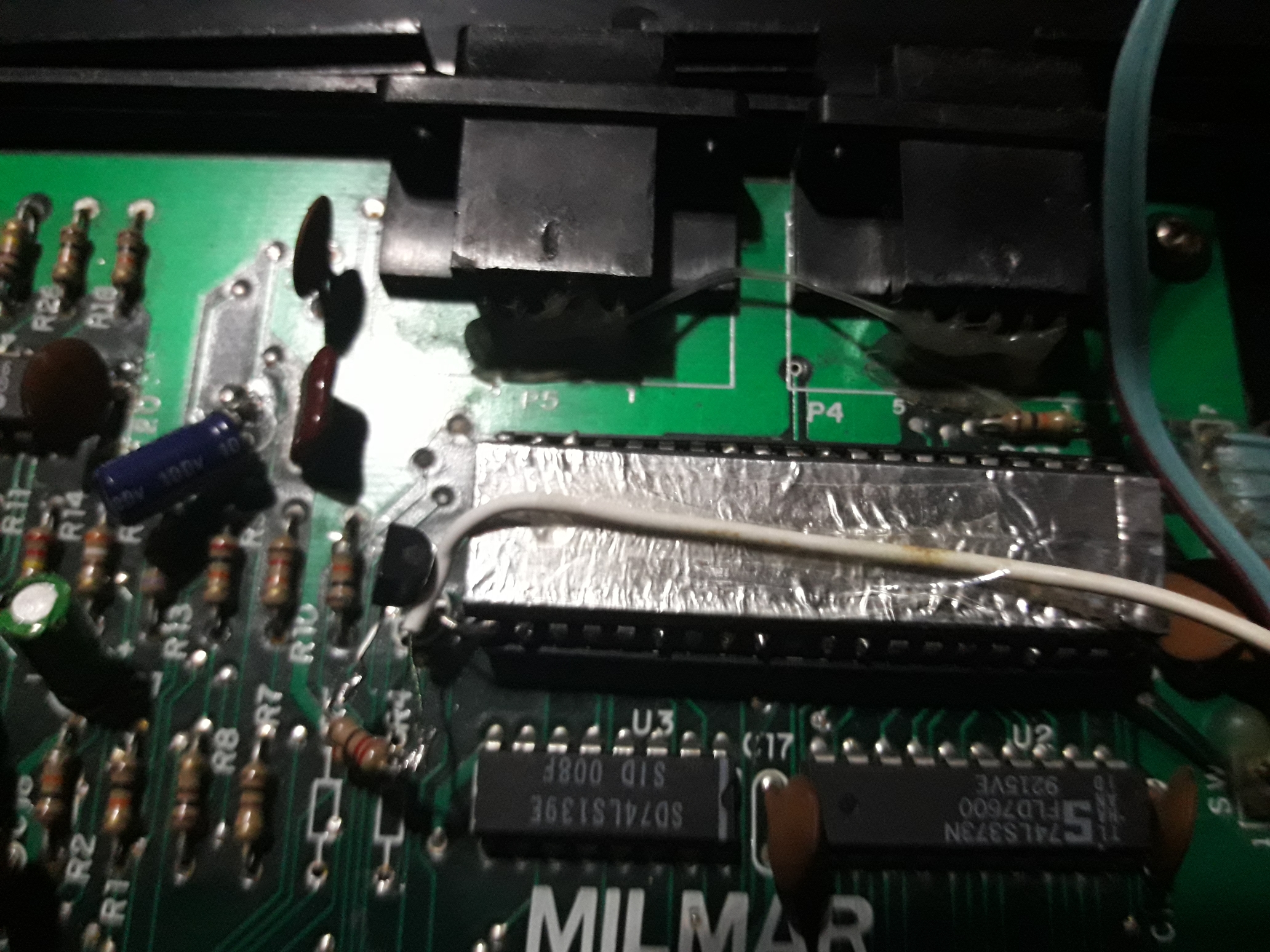
So, the reason I suggested replacing the 74HCU04 is that, on the NES, PPU A13 connects to the cartridge, and to an inverter in the 74HCU04.
The inverted form then goes to the cartridge, where it's usually (but not always) connected to the enable pin on the 2KiB of PPU RAM inside the NES.
So, if the signal is due to some kind of coupling with PPU A13 ... then by padding a little bit of a signal that's the opposite (NOT(PPU A13) out of the inverter), then maybe you can cancel out the jailbars?
lidnariq wrote:
So, the reason I suggested replacing the 74HCU04 is that, on the NES, PPU A13 connects to the cartridge, and to an inverter in the 74HCU04.
The inverted form then goes to the cartridge, where it's usually (but not always) connected to the enable pin on the 2KiB of PPU RAM inside the NES.
So, if the signal is due to some kind of coupling with PPU A13 ... then by padding a little bit of a signal that's the opposite (NOT(PPU A13) out of the inverter), then maybe you can cancel out the jailbars?
Interesting i had absolutely no idea. Do you know which pin on 74HCU04 Is the right inverter ?
lidnariq wrote:
https://console5.com/wiki/File:NES-001-Schematic---CPU,-PPU,-RAM,-CIC.png
Looks like pins 5 (PPUA13) and 6 (NOT PPUA13)?
You crazy SOB it worked.... it freaking worked ...
First I tried pulling PPUA13 to make sure I was not crazy and it was absolutely clear there was no jailbars at all.
So first I tried to add a resistance between the pin and its trace and it did nothing.
So I’ve tried you re crazy Inverter idea with a 83k resistance and ... it worked.
The jailbars are still visible but barely. I cut the resistance to make sure it was not just my hopeful eyes and BANG the jailbars were back.
But I know I can make it perfect. So just to be clear I need to add more « Not PPU A13 » signal , so a smaller resistance right ?
Man thanks so much. This experience has been frustrating but also incredibly rewarding. Your knowledge of the NES is absolutely mind blowing.
To be honest, mixing in a little bit of "NOT PPU A13" is a dirty hack, but I'm glad it's working for you.
The problem is that both sides of "too much" or "too little" being mixed in will look very similar—the only difference being it moving by 4 pixels left/right.
If, as you say, they don't move left/right when you add/remove the 82kΩ resistor, then, yes, you want to move towards a smaller value. You might be well served with a small (1k? 10k?) potentiometer for fine tuning.
lidnariq wrote:
To be honest, mixing in a little bit of "NOT PPU A13" is a dirty hack, but I'm glad it's working for you.
The problem is that both sides of "too much" or "too little" being mixed in will look very similar—the only difference being it moving by 4 pixels left/right.
If, as you say, they don't move left/right when you add/remove the 82kΩ resistor, then, yes, you want to move towards a smaller value. You might be well served with a small (1k? 10k?) potentiometer for fine tuning.
I've tried with a 10k potentiometer and it seems it's not strong enough. and in fact you were right, it seems the bars were deported to a few piwels with an 83 Ko
The interference I get is so strong that I seem to get the best results around the 200k. Does it sound possible to you ?
Also It seems that depending on the game, the interference will be more or less strong. For exemple it's absolutely atrocious on Super Mario Bros 2. Bad on Super Mario Bros 3 and light on Megaman 2.
I guess I need a bigger potentiometer to find the right value but I'm not sure there will be one working for all games / Situations.
romibraman wrote:
The interference I get is so strong that I seem to get the best results around the 200k. Does it sound possible to you ?
I don't even have a guess. You could say almost any value in the range of 10k to 10M and I'd believe it.
I meant to suggest a fixed resistor *and* a potentiometer, so that the minimum resistance is in a useful place
Quote:
Also It seems that depending on the game, the interference will be more or less strong. For exemple it's absolutely atrocious on Super Mario Bros 2. Bad on Super Mario Bros 3 and light on Megaman 2.
To me, that strongly implies that it's still a problem with the power regulation.
I dunno, have you tried to externally providing 5V to the board using a USB cable or something, skipping the regulator altogether?
Quote:
I guess I need a bigger potentiometer to find the right value but I'm not sure there will be one working for all games / Situations.
Yeah, the change from game to game does strongly imply that

lidnariq wrote:
romibraman wrote:
The interference I get is so strong that I seem to get the best results around the 200k. Does it sound possible to you ?
I don't even have a guess. You could say almost any value in the range of 10k to 10M and I'd believe it.
I meant to suggest a fixed resistor *and* a potentiometer, so that the minimum resistance is in a useful place
Quote:
Also It seems that depending on the game, the interference will be more or less strong. For exemple it's absolutely atrocious on Super Mario Bros 2. Bad on Super Mario Bros 3 and light on Megaman 2.
To me, that strongly implies that it's still a problem with the power regulation.
I dunno, have you tried to externally providing 5V to the board using a USB cable or something, skipping the regulator altogether?
Quote:
I guess I need a bigger potentiometer to find the right value but I'm not sure there will be one working for all games / Situations.
Yeah, the change from game to game does strongly imply that
Not through usb but when I was powering the PPU it was a totally different regulator .
Anyway I spent the last few hours testing different values and the results were puzzling.
First there is clearly a discrepancy between games.
Second, and this one is almost more annoying. There is also a discrepancy between colors. Remember this blue and red intro screen on SMB2. Without a resistance I had jailbars everywhere. Now with the resistance I get either a perfect red but strong jailbars on blue or much better blue but strong jailbars on red depending on the resistance value.
It means that even with a potentiometer I won’t get a perfect result.
I would need to entirely filter the PPu A13 signal and I’m not even sure it’s possible.
One thing to note, I’m not sure if it can give you ideas. To do my resistance test I had to run a wire from the inverter pin 6. Just touching the other end of this wire with my finger was amplifying the jailbars. I guess I was acting as a capacitor ? Remember at this point it was not even connected to the v signal.
romibraman wrote:
Second, and this one is almost more annoying. There is also a discrepancy between colors. Remember this blue and red intro screen on SMB2. Without a resistance I had jailbars everywhere. Now with the resistance I get either a perfect red but strong jailbars on blue or much better blue but strong jailbars on red depending on the resistance value.
I ... don't even know.
Maybe a picture?
Quote:
Just touching the other end of this wire with my finger was amplifying the jailbars. I guess I was acting as a capacitor ? Remember at this point it was not even connected to the v signal.
*that's* going to be you acting as an antenna, and parts of the video pathway receiving that and amplifying it.
I don't suppose you know anyone with an oscilloscope?
lidnariq wrote:
romibraman wrote:
Maybe a picture?
I don't suppose you know anyone with an oscilloscope?
I have ordered new bigger potentiometer. It will make make much better test, I’ll send a picture then, probably even a video.
I can try to find an oscilloscope , what test do you have in mind?
Thanks again for your help .
I guess I'd like to look at PPU A13, video out of the PPU, and +5V (AC coupled, DC block) at the same time? Each two pairwise would also be fine.