I'm trying to get a SNES working. The problem right now is that it won't power on. I've replaced the pico fuse, so I know that's OK. In poking around (and comparing it another SNES I have), I noticed that the voltage going into a diode labeled D1 on the motherboard and the schematic is 9V. Coming out the lead toward the switch, it is 3.3v. On the good motherboard, it is 9v at that point. While testing, I noticed that with the bad board plugged in, but the switch off (open), the voltage is 9v at the same place. This leads me to believe that there is something in the rest of the board, and not the diode itself that is the problem, but I could be wrong. I did a quick ESR check on the only two through hole radial electrolytic capacitors and they seemed fine. This is the SNS-CPU-GPM-01 motherboard, so it does not have the large 1000u capacitor at C67.
What would be the next thing to check? Any ideas?
Thank you very much for your help!
Dan
Did you just say that there's a 5.6V drop across a forward-conducting diode? Either there's a short somewhere after it, or the diode is toast. (Or the former has caused the latter)
Yeah, as the diode is between the switch and wall wart, it sounds like the diode is failing or something along the path is acting like a resistor. So when the switch is open, there's no load, so you get full voltage. Check the resistance from the + side of the diode to the barrel connector side of the jack. You've tested the wall transformer on another SNES, right?
honesty it could be any component after the switch that is a near short circuit.
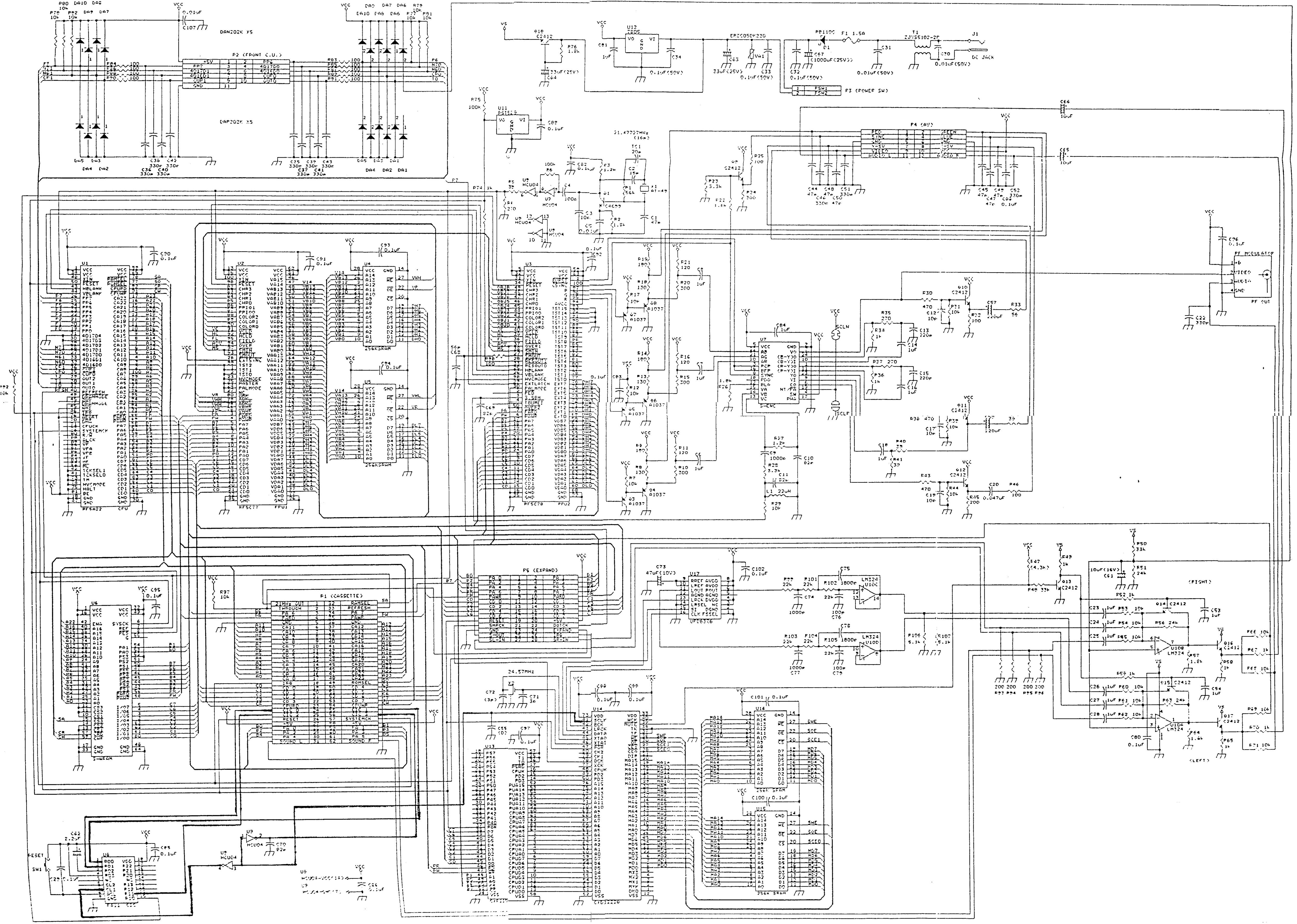
there are real schematics floating around the internet.
http://img37.imageshack.us/img37/8863/snscpugpm0102.pngJ1 in the top middle-right of the schematic here is the power input.
I see the diode D1 you are talking about.
I see the power switch is after the diode.
If there were any modifications made, check there first (disabling lockout chip and such).
Otherwise it's anything after the power switch (bypass capacitors, voltage regulator, internal shorts in chips, transistors).
You might get lucky and see a distressed component or burn marks, or you might never find it unless you literally ripped up everything, because after a certain point after the voltage regulator, the Vcc line is going to branch too many different ways.
Check the following:
on the 7805 regulator, there are three pins, in, gnd, and out.
2. Compare in to GND; it should be anywhere above ~7.5V.
1. Compare out to GND; it should be a solid 5V.
The SNES/SFC runs almost entirely on that 5V (except a small part of the audio section that needs the unregulated in from the adapter). If that 5V is anything but, it will not do anything.
If the IN looks good, but the OUT is not 5V, you may need a new 7805. In such a case, remove the regulator. Maybe test its pins to look for unusually low resistance (I can't provide this data right now but it should be available for the model).
Fortunately a 7805 is very cheap and not hard to find, nor difficult to solder.
If the 7805 *is* putting out 5V correctly, check around the board to see other areas that should be 5V, and see if they are.
EDIT: looks like you've already identified the problem being related to getting the 9V towards the 7805... still, if the 7805 is busted it may be pulling the 9V very low if its resistance is way too low. Of all the parts involved in that part of the power circuit the 7805 is probably going to be one of the first parts to fail and thus one of the first to be checked.
Wow! Thank you for all the good advice. Let's see now:
lidnariq - If the diode is bad, I'm not sure how I'll find another one. The only markings on it are one line with "S I" and a second line with "M", and one of the schematics has "PB1100". Google didn't yield much on that, so if the diode is bad, I don't have much to go on for getting a new one.
blargg - I did check the entire path, but at the time I was just checking for continuity, I didn't pay attention to the actual resistance. And yes, I did check the wall wart.
whicker - Thanks for the schematics. They are different from the set I found. The set I found is easier to read, but has less information. I've looked at the board and didn't see anything obvious. Now I guess I get to go back over it with a magnifying glass.
mikejmoffitt - The 7805 is after the switch, so - if the switch is open, then there is no voltage between the first pin and the ground (by design), and if the switch is open, then the voltage is 3.3V coming in, and .5V coming out. The 7805 needs at least 8v in to provide the 5v outs, so it can't function with only 3.3v. I wish it were the 7805, that would be much easier to find and replace than the diode.
Thank you for all your input! I'll let you know if I find the problem.
Dan
Try putting an ammeter in series with (or in lieu of) the power switch—if the current indicated is low, then you know the diode is wrong.
If the schematic whicker provided is correct, PB1000 is a schottky diode. Any medium-high current one (1-3A?) should be an acceptable replacement.
It took me a while to get back around to it, but I replaced the diode and now it powers up. I verified that the voltage regulator has 5 volts coming out (ok - 4.95).
The next problem is that I don't get video or audio.
Here's what I've tried:
1. Tested the RC adapter with another system. It works fine.
2. Tested with a multi-out cable from a good system. No change.
3. Tested continuity on each pin from inside the cartridge slot to the solder point on the bottom. That wasn't as much fun as I just made it sound. All connections were good.
4. I read on another forum that sometimes the reset button can get stuck closed, thus keeping the system in a constant "reset" state. I removed and tested the reset button, and it is fine.
What else can I check?
Thanks for your help!
Dan
Unfortunately, at this point, it's probably part of the SNES core (CPU, PPUs, or RAMs) that are dead. If you have an oscilloscope, you can poke around to find out whether any given component is doing something.
Quote:
3. Tested continuity on each pin from inside the cartridge slot to the solder point on the bottom. That wasn't as much fun as I just made it sound. All connections were good.
Any shorts between adjacent pins?
Note that an improperly-connected or malfunctioning SPC-700 can cause many games to freeze before they show anything, because their I/O code has no timeout.
Try powering the SNES post-power circuitry - give 5V to where the 7805 normally does, see if any problems change / disappear.