Hi all. Not sure if this is an appropriate place for this discussion, and I'm okay if this is moved to a better spot.
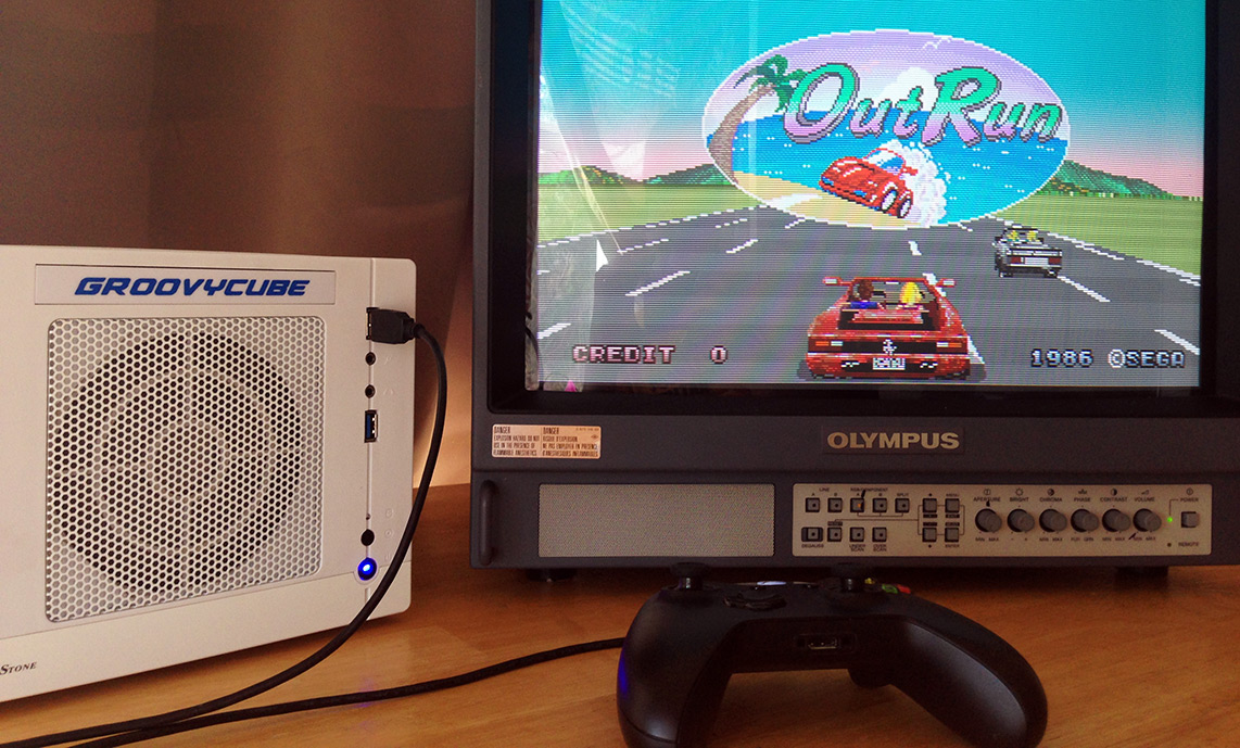
I've been trying since New Year's to make a general-purpose RGB>YPbPr encoder (and hopefully refining the result to also output S-Video and Composite) with basically no usable results. The end goal here is to have a small and simple circuit board that I could build into various consoles or into plug-and-play dongles to get my YPbPr CRT working with the Dreamcast, PS1, a PC that I built to be a console-ized arcade emulator and what have you.
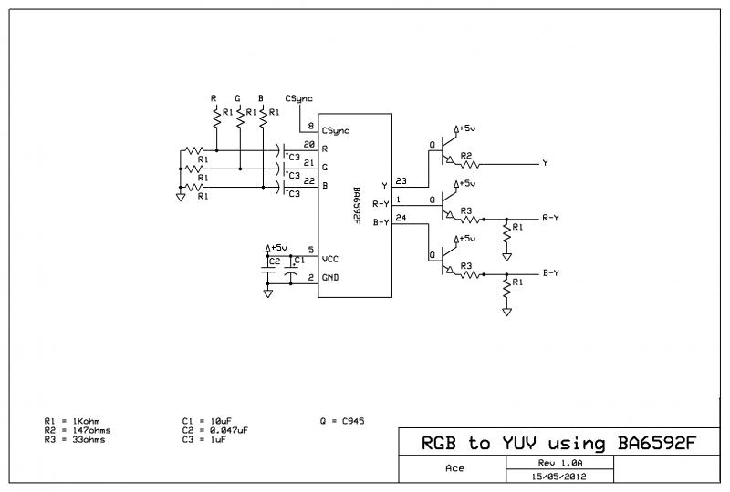
My most recent attempt focuses on the Snes' encoder, the S-ENC or BA6592F. I've found this schematic and I've been working from it, but I'm getting absolutely no picture from it. I've seen a few people talk about it here and I was hoping that someone could tell me what I need to do to this chip to get it to work.
Right now my setup is
Composite sync from Dreamcast > 22uF capacitor (remove DC coupling) > 75Ohm pulldown resistor > pin 8
+5V from the Dreamcast > 0.047uF capacitor to ground > 10uF capacitor to ground > pin 5
Ground from Dreamcast > pin 2
And if I understand at all how this thing works, I should get an empty sync signal out of pin 23. But instead, I get a very flat 1.4ish volts out of pin 23. Now, there is a lot of pins on this chip that I don't at all understand. Here's what I've got out of it:
And the schematic that I draw these guesses from.
I've tried a few other configurations by tying VCC to a few different pins but none of it seems to have effect on my Luma line. Does anyone here have any experience with this thing?
I've been trying since New Year's to make a general-purpose RGB>YPbPr encoder (and hopefully refining the result to also output S-Video and Composite) with basically no usable results. The end goal here is to have a small and simple circuit board that I could build into various consoles or into plug-and-play dongles to get my YPbPr CRT working with the Dreamcast, PS1, a PC that I built to be a console-ized arcade emulator and what have you.
My most recent attempt focuses on the Snes' encoder, the S-ENC or BA6592F. I've found this schematic and I've been working from it, but I'm getting absolutely no picture from it. I've seen a few people talk about it here and I was hoping that someone could tell me what I need to do to this chip to get it to work.
Right now my setup is
Composite sync from Dreamcast > 22uF capacitor (remove DC coupling) > 75Ohm pulldown resistor > pin 8
+5V from the Dreamcast > 0.047uF capacitor to ground > 10uF capacitor to ground > pin 5
Ground from Dreamcast > pin 2
And if I understand at all how this thing works, I should get an empty sync signal out of pin 23. But instead, I get a very flat 1.4ish volts out of pin 23. Now, there is a lot of pins on this chip that I don't at all understand. Here's what I've got out of it:
Code:
01 - Pr Out
02 - GND
03 - PCP? tied to bfp?
04 - SW - power off chip? Tied to VCC in SNES schematics
05 - VCC
06 - Chroma out
07 - Composite out
08 - Combined sync in
09 - Luma in? connects to 23 indirectly
10 - Pb in? connects to 24 indirectly
11 - Pr in? connects to 1 indirectly
12 - Blanking? - 10kOhm to ground in the SNES schematic
13 - volt c...?
14 - volt b...? indirectly tied to 13
15 - volt a...?
16 - Burst flag pulse?
17 - pha?
18 - pdo?
19 - NTSC/Pal switch tied to VCC in SNES schematic
20 - Analog Red in
21 - Analog Green in
22 - Analog Blue in
23 - Luma out
24 - Pb out
And the schematic that I draw these guesses from.
I've tried a few other configurations by tying VCC to a few different pins but none of it seems to have effect on my Luma line. Does anyone here have any experience with this thing?