What is the 3 pin oscillator??? that the dsp1 uses? And can a modern replacement be bought?
The blue blob linked to in this post in the link "SHVC-SOUND"? viewtopic.php?p=117718#p117718
It's a ceramic resonator, made of PZT. You can still get them, although ROHS compliance can make it harder.
It's a ceramic resonator, made of PZT. You can still get them, although ROHS compliance can make it harder.
I should have been more specific.... The resonator I'm referring to is from a Mario kart cartridge.
I don't know what blue blob you are referring to.
Anyways, so if I order a resonator, what frequency do I order?
Thanks!!
I don't know what blue blob you are referring to.
Anyways, so if I order a resonator, what frequency do I order?
Thanks!!
The number on it should indicate. e.g. https://en.wikipedia.org/wiki/Ceramic_resonator
Which number is relevant here?
Top number looks like 7600A
Lower number looks like 49_3
I assume kHz or is this in hz?
Thanks for any help. I really want to source a new part instead of robbing old parts from carts.
Top number looks like 7600A
Lower number looks like 49_3
I assume kHz or is this in hz?
Thanks for any help. I really want to source a new part instead of robbing old parts from carts.
Best guess is 7.6MHz.
http://www.assemblergames.com/forums/ar ... 35788.html mentions 7.6MHz in the context of repairing a DSP-1 board, too.
They don't seem to make all that many 7.6MHz resonators anymore; I'm not clear if anything bad will happen if you use something too slow (7.37MHz) or too fast (8 MHz). The above linked thread also points out that you can buy a full oscillator at the right speed and put it in, too. You can probably also manage to build/buy a inductor and capacitor that will resonate at the right frequency.
edit: couldn't stand to let stupid grammarfail remain
Thanks!
Sounds good to me if the original is through-hole.
Any particular reason you think it's specifically the resonator that's broken? They don't have all that many things that can go wrong with them.
Any particular reason you think it's specifically the resonator that's broken? They don't have all that many things that can go wrong with them.
lidnariq wrote:
Sounds good to me if the original is through-hole.
Any particular reason you think it's specifically the resonator that's broken? They don't have all that many things that can go wrong with them.
Any particular reason you think it's specifically the resonator that's broken? They don't have all that many things that can go wrong with them.
It's a through hole part. I was upgrading the super everdrive cart to the dsp1 and I wanted to use new parts (the HCU04 and the resonator). And for less than $1 it appears I can now.
Thanks for your help.
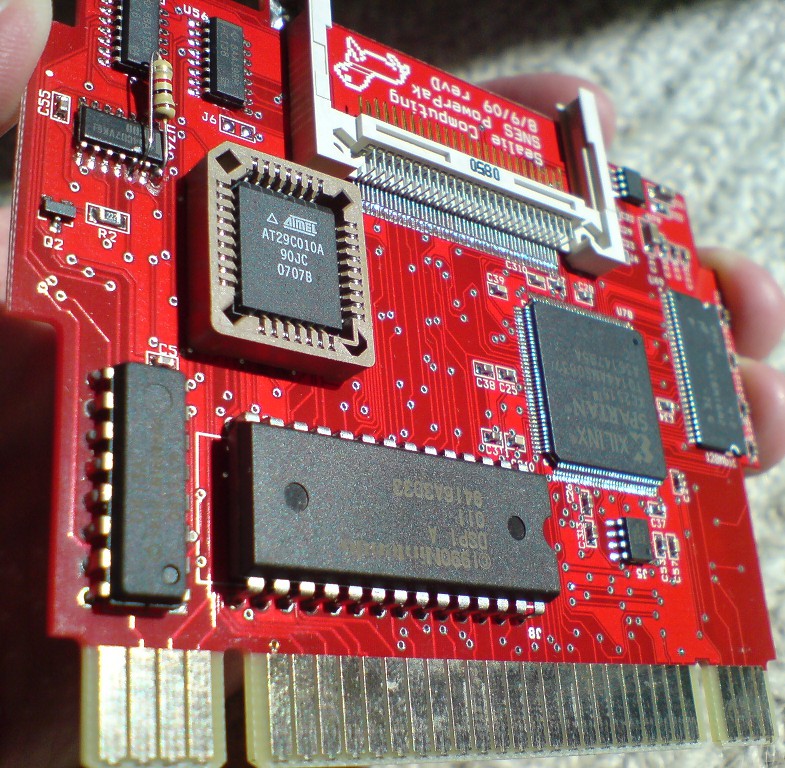
Wow, a photo showing the oscillator on DSP boards! That's one of the last and biggest SNES mysteries, I didn't believe that anybody would ever take a photo of it.
Yup, the photo looks like 7.600MHz, that's also matching up quite well with the uPD77C25 datasheet (which specifies max=8.192MHz).
But, the latest info from byuu (at least the latest that I am aware of), http://forums.bannister.org/ubbthreads. ... #Post66683 says 8.00MHz for DSP chips, where does that number come from? And which is right, or is it both true? There are various DSP1 games, plus some DSP2/DSP3/DSP4 games, plus the DSP1A/DSP1B revisions, so it's possible that some carts use 7.600MHz and some use 8.000MHz or even other clocks. Did anybody ever verify that?
PS. Duh, I just noticed that I do have a Super Mariokart PAL cartridge around here myself, that about the last unsolved mystery ;-)
Mine is using a "DSP1" chip, and a "[M]7600A, 271" oscillator (the package looks same as on Mark's photo, except that it's light blue, has a red dot on the top, and the "27" part is underlined).
Btw. the ST010 clock is also unclear:
http://wiki.superfamicom.org/snes/show/ST010 says 22.000MHz
http://forums.bannister.org/ubbthreads. ... #Post66683 says 10.00MHz effective (20MHz / 2)
http://wiki.superfamicom.org/snes/show/ST010 says 22.000MHz
http://forums.bannister.org/ubbthreads. ... #Post66683 says 10.00MHz effective (20MHz / 2)
DSP1: http://www.snescentral.com/pcbboards.ph ... VC-1K1X-10
DSP2: http://www.snescentral.com/pcbboards.ph ... VC-1B5B-02
DSP3: http://www.snescentral.com/pcbboards.ph ... VC-1B3B-01
DSP4: (no photo, sorry)
ST010: http://www.snescentral.com/pcbboards.ph ... C-1DS0B-01
ST011: http://www.snescentral.com/pcbboards.ph ... C-1DS0B-10
ST018: http://dforce3000.de/dmp/816_1261738278.png
Cx4: http://dforce3000.de/dmp/705_1261616456.png
I own boards for every special chip except for the OBC1 right now.
I lack a logic analyzer / oscilloscope, so I cannot clock these chips. But if you want photos, I can do photos.
Most of them are just solid white boxes. I went off of the MHz values written directly on the PCBs for my numbers.
If proven otherwise, I'd love to correct the values.
As it stands, I don't even know with certainty if every instruction on all of these takes one clock cycle, or more than that, or if it's a per-instruction deal.
Where do you see MHz values on the PCBs??? I see them on ST018 and CX4 boards, but not on DSP1-DSP4 or ST010/ST011 boards.
Hmmm, do you mean that oscillators are really "just solid white boxes" without any part numbers? My own cartridge and Mark's cartridge (see above phote) DO have part numbers though. The snes central ST011 photo does also show "15.something" on the ST011's ceramic oscillator. If you could make photos of the DSP/SETA oscillators or scribble down their part numbers would be great! If you do so: Please also include info which game it is, and if it's using one of the DSP1A/1B revisions.
I've my SNES in storage at the moment so I can't measure the clock (using an oscilloscope won't give very precise results anyways).
The datasheet isn't too clear about per-instruction timings. As I do understand it, they do simply mean that all instructions take 1 clock cycle. With the internal memory (and with it being separated into code & data areas) it should be possible to get that 1 cycle speed. The multiply function is probably executed on every opcode (no matter if the opcode does read/write the multiply result/parameters), if so, then multiplication shouldn't take any extra time either.
ST010 - Exhaust Heat 2 (Japan)

ST018 - Morita Shogi 2 (Japan)

ST018 - Morita Shogi 2 (Japan)
Oh, look at that, they're on the side.
Well, I didn't want to get the camera out, so you'll have to take my word for it.
[DSP1] Pilotwings (M7600A \ 0 N 2)
[DSP1A] Super 3D Baseball (M7600A \ 36 3)
[DSP1B] 3D Ballz (M7600A \ 53 1)
[DSP2] Dungeon Master (M7600A \ 1 0 1)
[DSP3] SD Gundam GX (M7600A \ 42 3)
[DSP4] Planet's Champ - TG3000 (M7600A \ 52 1)
[ST010] Exhaust Heat II (M22000C \ 31 2)
[ST011] Hayazashi Nidan Morita Shougi (15.00X \ G1 Q)
[ST018] Hayazashi Nidan Morita Shougi 2 (M21440C \ 50 3)
[Cx4] Rockman X2 (20.0MC \ T D K Y)
[Cx4] Rockman X3 (M20000C \ 5N 1)
[SA1] Mini Yonku Shining Scorpion 4WD (no crystal)
[SPC7110] Tengai Makyou Zero - Far East of Eden (no crystal)
[Mario Chip 1] Star Fox (no crystal, but there's a capacitor where it normally would be, PCB labels it L1)
[GSU1] Wildtrax (21.4MC \ TDK T)
[GSU2] Super Mario - Yoshi's Island (M21440C \ 30 2)
DSP1B had a tiny bit of grime on the 6, so it looked a little like M7800A. But I really doubt it's the one exception.
ST011 was the only ceramic clock, and it was really, really hard to read, even with a magnifying glass. The G1 Q part is suspect.
Thanks for pointing this out. Looks like my timing for the DSP1-4 was a little bit too fast.
byuu wrote:
[Mario Chip 1] Star Fox (no crystal, but there's a capacitor where it normally would be, PCB labels it L1)
[
[
Isn't a "L" designation for an inductor? Don't have a Yi near me at the moment.... You sure it's a cap?
Markfrizb wrote:
byuu wrote:
[Mario Chip 1] Star Fox (no crystal, but there's a capacitor where it normally would be, PCB labels it L1)
Isn't a "L" designation for an inductor? Don't have a Yi near me at the moment.... You sure it's a cap?Yeah, L is usually an inductor.
There's two pertinent boards here, both are odd:
SHVC-1C0N5S-01
- has pads for a SMT 74'04 but has a through-hole inductor surface mounted between the pins of where the first inverter would have been. (Inductors in this form factor are often green.)
SNSP-1C0N5S-01
- is the one Byuu is talking about, where it's just a generic SMT rectangular prism. But yeah, it's labeled L1, and so I'd assume it's an inductor. SMT prism inductors are usually really low inductance, though; it's hard to get more than a few microhenries in one.
Given that neither board has a 74'04, I have to assume the MARIO CHIP has an internal clock source, an internal oscillator driver (and the inductor is used in its self-resonant mode), or it's fed off the 21MHz from the cartridge edge. snescentral only has one side of the PCBs, though, so I can't look for myself.
lidnariq wrote:
, or it's fed off the 21MHz from the cartridge edge. snescentral only has one side of the PCBs, though, so I can't look for myself.
The second part of what you said.
If you half an incoming frequency using a divide by 2 circuit (basically a DFF toggling), you get a really nice 50-50 square wave no matter what distorted garbage comes in. But to get the chip to run at the 21 MHz, well, then you have to have an on-board oscillator.
Thanks for writing down the part numbers & thanks for the photos! After updating the fullsnes.htm timing sections... these are the currently known cartridge/expansion clocks:
Newly added values are DSPn=7.600MHz and confirmed/corrected ST010=22.000MHz. And just discovered: SNES central does now have S-DD1 bottom side pics at http://www.snescentral.com/article.php?id=0046 - revealing that the board uses the SNES master clock, too.
Only missing value in the above list is the S-RTC clock source (probably 32.768kHz or 32.000kHz, not that it'd be too important, the RTC seconds output should be certainly 1Hz either way).
Interesting theory... makes sense (at leats if the 21MHz SNES master clock is distorted (I've never checked that), or if it has some unexpected voltage). A workaround could be some divide-by-2 then multiply-by-2 circuit (but yeah, it may be cheaper/easier to use an on-board oscillator).
Code:
DSPn 7.600MHz Plastic Type "[M]7600A" (used without divider)
ST010 22.000MHz Plastic Type "[M]22000C" (internally 11.000MHz)
ST011 15.000MHz Ceramic Type "15.00X" (used without divider)
ST018 21.440MHz Plastic Type "[M]21440C"
CX4 20.000MHz Plastic Type "[M]20000C" or "20.0MC/TDKY"
MC1 <master> SNES Master Clock
GSU1 21.4MHz Plastic Type "21.4MC/TDKT"
GSU2 21.44MHz Plastic Type "[M]21440C"
SA-1 <master> SNES Master Clock
S-DD1 <master> SNES Master Clock
SPC7110 <master> SNES Master Clock
SGB <master> SNES Master Clock
SGB2 20.9MHz External oscillator (located on PCBs solder-side)
BS-X 18.432MHz Satellaview Receiver Unit (on expansion port)
RTC-4513 32.768kHz On-chip 32.768kHz quartz crystal in RTC chip
S-3520 32.768kHz External 32.768kHz quartz crystal (SFC-Box)
S-RTC ? kHz External unknown-frequency crystal
ACE <dotclk> SNES Dot Clock (Exertainment RS232 on expansion port)
Newly added values are DSPn=7.600MHz and confirmed/corrected ST010=22.000MHz. And just discovered: SNES central does now have S-DD1 bottom side pics at http://www.snescentral.com/article.php?id=0046 - revealing that the board uses the SNES master clock, too.
Only missing value in the above list is the S-RTC clock source (probably 32.768kHz or 32.000kHz, not that it'd be too important, the RTC seconds output should be certainly 1Hz either way).
whicker wrote:
If you half an incoming frequency using a divide by 2 circuit (basically a DFF toggling), you get a really nice 50-50 square wave no matter what distorted garbage comes in. But to get the chip to run at the 21 MHz, well, then you have to have an on-board oscillator.
Interesting theory... makes sense (at leats if the 21MHz SNES master clock is distorted (I've never checked that), or if it has some unexpected voltage). A workaround could be some divide-by-2 then multiply-by-2 circuit (but yeah, it may be cheaper/easier to use an on-board oscillator).
Either way, I suspect the inductor is there to serve as a current-mode lowpass filter, cleaning up the input so that any overtones of 21MHz are filtered out.
So should we be emulating the M21440C as 21440000hz or as 21477272hz?
I'm sure you are right. I don't even know what an inductor is. It was cap-like (eg cyllindrical.)
It used the SNES 21MHz clock at half frequency. I definitely recall hearing that even this was unreliable, which explains why GSU1 boards have their own crystal. But I wonder how unreliable it is since Star Fox / Mario Chip 1 runs just fine.
Sure. Since you're probably the only other person alive who would ever even consider this ...
How do you feel about emulating the tolerances of these oscillators?
For instance, a clock rate may nominally be 21477272hz (or 21440000hz maybe?), but in practice, the clock rate varies by a small amount. And for ceramic types, by a larger margin. And the clock can fluctuate a bit as it heats up, and each chip can have their own variances despite being the same part.
Do you think it'd be a good thing to introduce some volatility to the clock rates? It might help to catch software that is really poorly written and only works due to an -exact- clock alignment. Such software would fail in many systems, so catching it might be beneficial.
Quote:
Isn't a "L" designation for an inductor? Don't have a Yi near me at the moment.... You sure it's a cap?
I'm sure you are right. I don't even know what an inductor is. It was cap-like (eg cyllindrical.)
Quote:
Given that neither board has a 74'04, I have to assume the MARIO CHIP has an internal clock source
It used the SNES 21MHz clock at half frequency. I definitely recall hearing that even this was unreliable, which explains why GSU1 boards have their own crystal. But I wonder how unreliable it is since Star Fox / Mario Chip 1 runs just fine.
Quote:
Thanks for writing down the part numbers & thanks for the photos!
Sure. Since you're probably the only other person alive who would ever even consider this ...
How do you feel about emulating the tolerances of these oscillators?
For instance, a clock rate may nominally be 21477272hz (or 21440000hz maybe?), but in practice, the clock rate varies by a small amount. And for ceramic types, by a larger margin. And the clock can fluctuate a bit as it heats up, and each chip can have their own variances despite being the same part.
Do you think it'd be a good thing to introduce some volatility to the clock rates? It might help to catch software that is really poorly written and only works due to an -exact- clock alignment. Such software would fail in many systems, so catching it might be beneficial.
byuu wrote:
So should we be emulating the M21440C as 21440000hz or as 21477272hz?
As it reads 21440, it should be clearly 21.440xxxMHz. There might some reason why haven't used 21.477272Mhz: Probably the 21440 part was just cheaper, or maybe they wanted to avoid video interference, or (unlikely) 21.477 was too fast for the chip.
Of course, emulating it as 21.477272Mhz would be ways easier and won't make too much of a difference.
byuu wrote:
I'm sure you are right. I don't even know what an inductor is. It was cap-like (eg cyllindrical.)
Actually, that shape is more common for resistors (small capacitors usually look more like flat pan-cakes).
An inductor is a piece of wire wrapped around a metal core. Like all wires it does (basically) just work as this: You input a voltage at one end, and it does output the same voltage at the other end. Which is just boring. The thing doesn't do much.
The special feature is that it behaves like a heavy wheel that gets accellerated by the electrons flowing through it. If you increase/decrease the voltage then it will rotate faster/slower, but as it acts like a heavy wheel it will take some time, and won't accellerate/deaccelerate instantly. In practice: It will keep a constant output voltage even if the input voltage goes up or down for a moment.
It could be used to eliminate high frequency noise (unlikely in this case, as it shall certainly pass the 21MHz, and I can't see where higher frequency noise could come from). Or (more likely & as lidnariq said) it's intended to filter out overtones. Eg. if the SNES were outputting something like a 21MHz square-wave, then the signal would (try to) accellerate the wheel instantly on raising and falling edges, but the inductor would refuse to pass the voltages like that, and instead it would spit-out some kind of 21MHz sine-wave.
byuu wrote:
How do you feel about emulating the tolerances of these oscillators?
I wouldn't go that far as doing that. And it would have it's ups and downs. Normal users (gamers) will probably just want the game to work as intended, they won't appreciate it if you make the emulation more unstable (unless a game should rely on unstable timings).
It might be useful for developers, though if you are doing it behind their back, then they won't have a clue why their games are crashing once or when. Best might be some stress test option with maybe 4 settings (Normal Clock, Slightly Faster, Slightly Slower, and Randomly Increasing/Decreasing Clock).
I doubt that there are too many developers for co-processor games, but for the APU it might be actually useful.
I wonder what clock signal the SNES PowerPak feeds to the DSP-1, given the fact that there doesn't seem to be any crystal on the PCB ... 
byuu wrote:
Do you think it'd be a good thing to introduce some volatility to the clock rates? It might help to catch software that is really poorly written and only works due to an -exact- clock alignment. Such software would fail in many systems, so catching it might be beneficial.
There are advantages and drawbacks to simulating oscillator frequency ratio variance. The advantage, as you said, is that poorly written programs fail fast on the developer's machine. The drawback is that changing the ratio may change whether or not waiting for the DSP to finish causes a lag frame, breaking movie playback.
byuu wrote:
Quote:
Given that neither board has a 74'04, I have to assume the MARIO CHIP has an internal clock source
It used the SNES 21MHz clock at half frequency. I definitely recall hearing that even this was unreliable, which explains why GSU1 boards have their own crystal. But I wonder how unreliable it is since Star Fox / Mario Chip 1 runs just fine.lidnariq wrote:
One needs some kind of active logic to divide a frequency by two. (Is there some inside the MARIO CHIP?)
Yes - at least optionally: The CPU and the Multiply Unit of the MC1/GSU1/GSU2 can be configured to run at full speed or half speed (there are I/O ports that allow to do that configuration by software). Starfox and (most) GSU1 games are running the CPU at half speed (=around 10MHz). Don't know which multiply speed they do use.
byuu, unless you're going to start emulating delays down to the gate level within individual chips, emulating oscillator variance isn't likely to do anything useful...
Ramsis, if I had to guess, I'd say the PowerPak is generating the clock signal in the FPGA, they tend to have built in hardware for generating all sorts of clock multipliers/dividers. In turn, I'd guess the FPGA is using the SNES Master Clock signal from the cart edge as its clock source.
Also, from the SNESCentral pics of the S-RTC board, that's just a run-of-the-mill 32.768KHz tuning fork. It gets fed into a 16-bit counter in order to get out millisecond clock ticks. So, mystery solved, you now have all of them.
qwertymodo wrote:
byuu, unless you're going to start emulating delays down to the gate level within individual chips, emulating oscillator variance isn't likely to do anything useful...
Well yes, there may be cases where one might need to count timings in fractions of clock cycles, or cases where a signal is just changing so it is neither stable High nor stable Low. But simple timing problems could be emulated. For example an APU uploader that sends data at 100Kbyte/s, but can receive only 99Kbyte/s at the remote side.
qwertymodo wrote:
Also, from the SNESCentral pics of the S-RTC board, that's just a run-of-the-mill 32.768KHz tuning fork. It gets fed into a 16-bit counter in order to get out millisecond clock ticks. So, mystery solved, you now have all of them.
The http://www.snescentral.com/pcbboards.ph ... VC-LJ3R-01 photo doesn't show a part number. Or are those tiny cylindrical oscillators always having 32.768kHz?
I think I have also came across circuits that used "32kHz" in the past... but maybe they did mean kilo=1024 in that circuits. And aside from the 32.xxxkHz range, theoretically it should be even possible to put something like a 20MHz quartz into that package.
Where do you have the info about the "16-bit counter" from? Do you have a matching Sharp datasheet?
nocash wrote:
Or are those tiny cylindrical oscillators always having 32.768kHz?
That form factor (especially pay attention to diameter) seems to always be in the tens of kilohertz range. It doesn't necessarily have to be 32KiHz; I'm pretty certain I've seen things in that form factor all the way from 10kHz up to 60kHz or so. Quote:
I think I have also came across circuits that used "32kHz" in the past... but maybe they did mean kilo=1024 in that circuits.
That seems to be more or less the only place where everyone uses kibihertz: 32kHz almost always means 32768Hz. I think it's because it, with a 15-bit counter, makes it utterly trivial to get out a 1Hz clock source for miscellaneous things. nocash wrote:
And aside from the 32.xxxkHz range, theoretically it should be even possible to put something like a 20MHz quartz into that package.
I believe the cut of the quartz crystal needed for the frequency range imposes some constraints on housing size and shape; I tentatively think you couldn't get a 20MHz crystal in that specific form factor.nocash wrote:
Where do you have the info about the "16-bit counter" from? Do you have a matching Sharp datasheet?
Almost all battery-backed RTCs work the exact same way; a 32KiHz crystal divided in silicon to produce a clock pulse rate anywhere between 2⁰ and 2¹⁵. (e.g. the gameboy's MBC-3)nocash wrote:
qwertymodo wrote:
Also, from the SNESCentral pics of the S-RTC board, that's just a run-of-the-mill 32.768KHz tuning fork. It gets fed into a 16-bit counter in order to get out millisecond clock ticks. So, mystery solved, you now have all of them.
The http://www.snescentral.com/pcbboards.ph ... VC-LJ3R-01 photo doesn't show a part number. Or are those tiny cylindrical oscillators always having 32.768kHz?
I think I have also came across circuits that used "32kHz" in the past... but maybe they did mean kilo=1024 in that circuits. And aside from the 32.xxxkHz range, theoretically it should be even possible to put something like a 20MHz quartz into that package.
Where do you have the info about the "16-bit counter" from? Do you have a matching Sharp datasheet?
My info about the 16-bit counter is just because "that's the way it's done", you take a 32.768kHz (often referred to in shorthand as 32kHz, but in the case of a RTC oscillator, it's going to be 32.768kHz, not 32.000kHz), and you feed that signal into a binary counter gives you a 1/2 frequency divider per (n-1) bits, so that the MSB of a 16-bit counter clocked at 32.768kHz switches from 1 to 0 and back again at a rate of exactly (omitting tolerances) 1s, which is used as the RTC clock source. I'm pretty sure that using a 1Hz oscillator directly would have pretty horrible drift in terms of tolerance vs doing it this way.
As to whether or not you can get MHz frequencies in the same package, yes you can. However, the fact that it is being used as a RTC basically means 99% certainty it's a 32.768kHz. If you REALLY want to confirm it, then you'll have to get better photos, or get your hands on one. But it's a pretty safe bet that I'm right
Edit: I forgot how to math... 32,768Hz * 2 ^ -15 = 1s, not 1ms
qwertymodo wrote:
As to whether or not you can get MHz frequencies in the same package, yes you can.
If you filter by diameter (< 0.1" diameter), I only see stuff below 160kHz.lidnariq wrote:
qwertymodo wrote:
As to whether or not you can get MHz frequencies in the same package, yes you can.
If you filter by diameter (< 0.1" diameter), I only see stuff below 160kHz.It was more a matter of admitting that I couldn't definitively ID the part by the package alone, which my original post may have implied. Even finding "only stuff below 160kHz" still means that the crystal *could* be any of those frequency values, and that the radial can package isn't unique to the 32kHz crystals. But in this particular case, I'm still fairly confident that's what it is.
nocash wrote:
The http://www.snescentral.com/pcbboards.ph ... VC-LJ3R-01 photo doesn't show a part number.
KDS6F
Markfrizb wrote:
http://www.mouser.com/Search/ProductDetail.aspx?R=CSTLS7M68G53-A0virtualkey64800000virtualkey81-CSTLS7M68G53-A0
This looks pretty close. Any reason why not?
This looks pretty close. Any reason why not?
I can confirm that this part works in Mario kart.