How Reemplaze MAD-1 with 74LS186 (accepting 32 Bits in Rom)?

This is an archive of a topic from NESdev BBS, taken in mid-October 2019 before a server upgrade.
View original topic
How Reemplaze MAD-1 with 74LS186 (accepting 32 Bits in Rom)?
by on (#116590)
hello friends, before you get started I want to mention that there is a program that transforms rom low to high ("SnesConv")

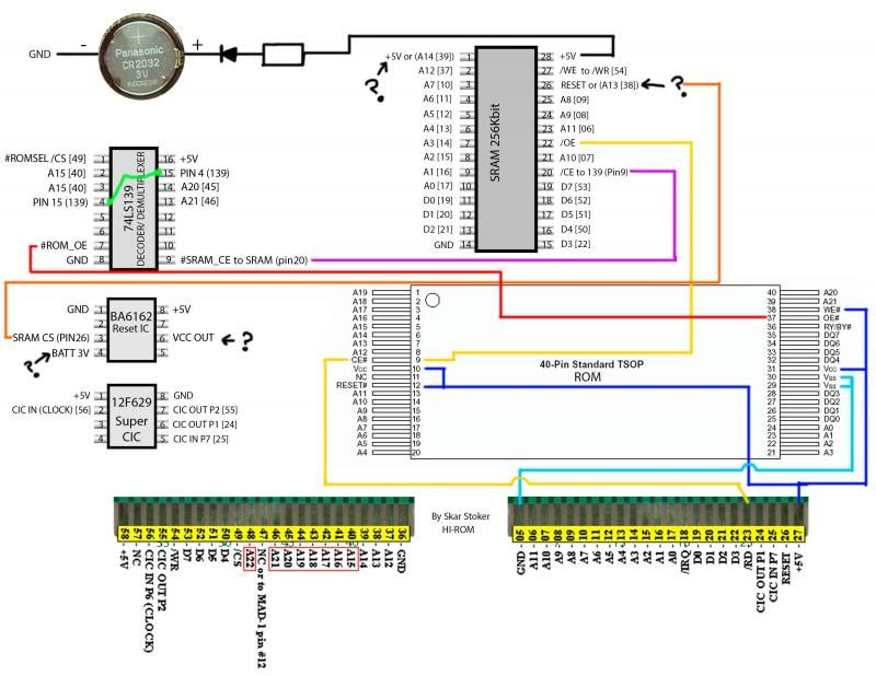
Reading most of the forum, I can find more information and I have come to this scheme, (using most of the information in this thread and others) the numbers enclosed in square brackets refers to the cartridge pins

Image

but I have several problems
not if it really works, my pic programmer still does not arrive, so I can not try, please, someone could verify that everything is properly connected to where it should go, I would appreciate any help forever, suggestions, among others.

doubts are marked with exclamation marks (?)
in BA6162
VCC OUT should to go a GND ?
BATT 3V is connected to the positive of the battery?

in SRAM
pin1 must conectarce to 5v or pin14?
pin 26 must be connected to A13 or should go to BA6162 pin 26


Finally, I recently learned basic electronics (Ohm law, Kirchhoff's law, etc..) Is not much, please someone, good person who could help

sorry for my bad English
regards


PS: ikari_01 Special thanks for their SuperCIC, thanks for sharing your work with us, and not be selfish with their wisdom and talent

also thank you very much to Magno, getafixx, infiniteneslives, whicker, lidnariq, qwertymodo, MottZilla, Markfrizb for the help on MAD-1, among other important information in other threads
Re: How Reemplaze MAD-1 with 74LS186 (accepting 32 Bits in R
by on (#116641)
First of all, give special thanks to qwertymode for the help and whicker by its schema, I could finally understand some things I can help find a solution to my problem.

starting from the beginning, 74lsn139 is a double decoder, where two signals enter and exit 4 signals (abstract example: in a radio, where by a knob, we choose if we want to hear cassette (exit1), radio (exit2), dvd (exit 3), or auxiliary(exit 4)) then we have two decoders into a single IC.

see the next picture
Image

explaining superficially so you can understand, I'm human, so I can go wrong

if pin1 send you current, all outputs are disabled, otherwise, depends on the signals sent to pin 2 and pin 3, to choose the output (pin 4 to pin 7).

no signal on pin 1:
if pin 2 and 3, no electrical signal sent by default you enable the output pin 4.
pin 2 no signal, and send signal to pin 3 was enabled output signal pin 6
pin 3 no signal, and send signal to pin 2 was enabled output signal pin 5
if we send signal to pin 2 and pin3 will activate the output signal pin 7

then reviewing previous threads, I can finally understand these two images (Thank magno and getafixx, Thanks for sharing your experience with us )

MAGNO
Image


following the magno's image
1.-From / ROMSEL, it sends a signal to enable or disable the outputs of the 74LS139

2.-From pin 40 of the cartridge (A15) is connected to pins 2 and 3 of the decoder, then when the game doesn't this savegame, output was enabled decoder pin 7 (which is connected to maskrom)

3.-Then when the game needs savegame, signal cartridge pin 40 (A15) stop sending signal (LOW signal) and block the output pin 7, but in turn has enabled this output pin 4.

if you look pin4 is connected to another pin (do not forget that this IC are two decoders in one) to pin15, this enabled this the second decoder, and most likely the pin 14 (A20 [45]) and pin 13 (A 21 [46]) signal being sent when shooting, so activating the output pin 9 (which is connected to the SRAM)

then this should work well only if my next hypothesis was well

when the game is functioning normally (without saving)
pin 15 should be sending signal
pin 20 and 21, in this case it would imply I was or not sending signal.

when the game prompts you to save
pin 15 should stop sending signal (I mean sending a signal LOW)
pin 20 and pin 21, both should be sending signal


this configuration only work one MASKROM and one SRAM


the part you do not understand is what he said qwertymodo, which can only handle 16 Mbits. I think that with an EEPROM (flash) of 32 Mbits should work.


keep writing soon, I need some sleep, I'll have a nice nightmare with the MAD-1
Re: How Reemplaze MAD-1 with 74LS186 (accepting 32 Bits in R
by on (#116642)
Are the B and A swapped in one of the tables in that graphic?
Re: How Reemplaze MAD-1 with 74LS186 (accepting 32 Bits in R
by on (#116663)
tepples wrote:
Are the B and A swapped in one of the tables in that graphic?


I read your question several times and I do not understand, of all schemes, to which you refer?

explaining a little more, 74LS139, discarding the pin 8, which is connected to GND, and pin 16 is connected to +5 V

the first decoder is made from pin 2 to pin 7, and the second decoder is made from pin 9 to pin 15. if you look both internally decoding scheme are independent, are not linked.

The pin 1 of the first decoder, like the pin 15, acts as a switch that turns on or off a light bulb in the case of the decoder, this enables or disables the outputs of IC

pin 2 and pin 3, corresponding to A and B, this is where, depending on the signals that are sent output is enabled or disables (pin 4 to pin 7)

if you use only one entrance to handle the outputs would remain like this:

send signal pin 2 (Signal HIGH)
pin 3 connected to +5 V (HIGH signal always)
output enable to pin 7

pin 2 sends no signal (LOW signal)
pin 3 connected to +5 V (HIGH signal always)
output enable to pin 6


I hope to have successful your question

regards
Re: How Reemplaze MAD-1 with 74LS186 (accepting 32 Bits in R
by on (#116665)
I see G, A, B in one table and G, B, A in the other.
Re: How Reemplaze MAD-1 with 74LS186 (accepting 32 Bits in R
by on (#116667)
tepples wrote:
I see G, A, B in one table and G, B, A in the other.


wuajajaja :lol:
I'm sorry, I must have been very sleepy when I wrote this, I get right that problem, so you do not misunderstand

answering your previous answer is no, not interchangeable


greetings and thanks for noticing the mistake, I will correct now

EDIT: FIX