Sweet vintage RGB tv pick-up. TV experts, what do I have?

This is an archive of a topic from NESdev BBS, taken in mid-October 2019 before a server upgrade.
View original topic
Sweet vintage RGB tv pick-up. TV experts, what do I have?
by on (#84279)
I picked up a vintage TV yesterday off kijiji that was too cool to ignore, but I need some help from tv experts to help me figure out what I have to get the most from it. I bought a Panasonic 24" Color TV from 1984 that's loaded with features. I have no doubt in my mind that this would have been one EXPENSIVE tv back then. The TV in case anyone can find any info other than replacement parts is a Panasonic PC-26K79RS.

Image
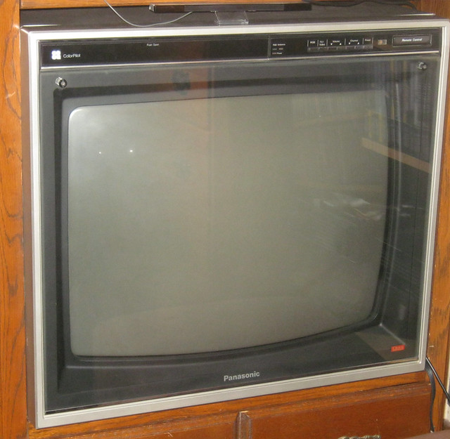
So check this tv out! it's a 24" CRT with a glass screen protector! I've never seen anything like that outside of arcade cabinets! and it's in such good shape after all these years!

Image
This TV oddly has some sort of windowed vents on each side of the tv. What's with that?

Image
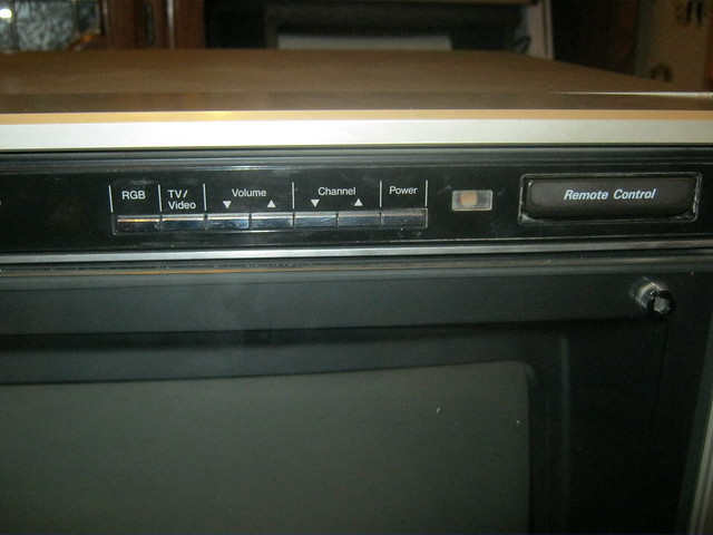
This is what caught my eye. Notice where it says RGB?

Image
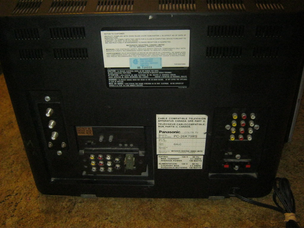
The back of the TV. Check out all the inputs this thing has!

Image
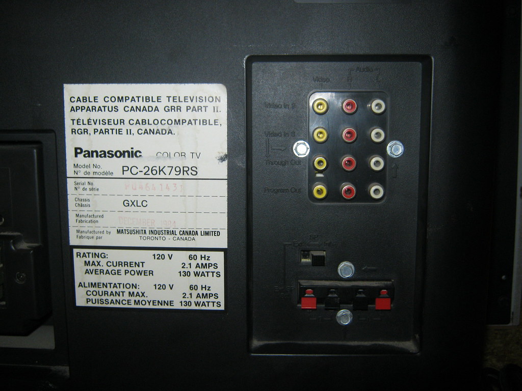
The right side of the TV has two sets of composite inputs (the first is on the right side) and two others I have no idea what they are/do: "Through Out" and "Program Out". Can anyone help me figure out what these are?

Also note that it's got hookups for external speakers. Pretty cool. I'm going to have to try that.


Image
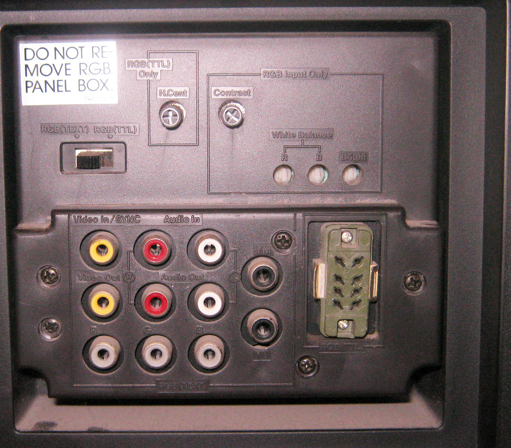
Here's the real star of this show - an RGB Panel Box(!).
I don't pretend to be anything of an expert on RGB via tvs, but I know that whatever this is it isn't SCART. I have so many questions about this I don't know where to begin.

There's a switch between RGB (TEXT) and RGB (TTL). What do each of these mean?
What is the olive green 8 pin connector?
What about all those other inputs? What about the YM and YS ports? the more info I can get on everything this panel box does the better!

I'm crossing my fingers I'll somehow be able to use this to perhaps get some RGB system to work. Perhaps there's some sort of TTL to SCART adapter? In any case I just want to figure out what I got. Thanks in advance!

by on (#84284)
I remember seeing a number of TVs in the 80s with the (plexi?)glass shield like your picture.

I'm certain the side panels are to allow the speakers (you can see the grill) to be narrow-profile when shipped but reflect sound when installed.

The RGB(TEXT)/RGB(TTL) switch is almost certainly a toggle between the RCA inputs and the funny green connector -- which is an EIAJ connector (http://www.labguysworld.com/Connectors.htm, http://www.riscos.org/legacy/monitor.html). I'd guess TEXT is for a teletext decoder, probably R/SoG/B and TTL may be for CGA compatibility.

by on (#84400)
Based on the legend, I'm going to guess that the "Through Out" is a direct re-output of the Video 3 input, and "Program Out" would contain whatever is being displayed on the set at the moment (dunno whether it only passes through CVBS sources, or if it encodes RGB to CVBS for that purpose). I'm also going to guess that's not SoG, since that CVBS input on the RGB module is also repurposed for sync.

Look in the middle of that "vent" - it's a speaker grille. Probably has a cover since this seems to be an industrially-targeted TV, and it has speaker-level output, so if the internal speakers weren't being used, they could be covered up and protected from dust/damage/etc.

Edit: Heh, doesn't seem like there's much info about this set on the internet. Googling that model number results in two links to sites selling manuals, and about fifteen various links to this thread and the one over at Digital Press.

by on (#84722)
doesn't seem to have the typical RGB input(s) that I have ever seen, and I have personally owned several RGB sets. Most RGB sets habe BNC, VGA connectors or both, and support 15khz/31khz. I wonder, do you have an RGB capable NES/famicom?

by on (#85834)
new video showcasing more of this awesome tv.

http://www.youtube.com/watch?v=ctnFFU9FXJ8

by on (#85843)
Found the pinout for the RGB(TTL) connector: http://nfggames.com/forum2/index.php?topic=4308.0

Reproduced here in text in case the image ever goes away:

Code:
DIGITAL RGB input connector

 4 3 2  1
+--------+
|O O O  O/
|O O O  O\5
+-------|+
 8 7 6 ///

Pin. No.  Signal           Signal Level
1         Intensity input  High: *    Low: Half tone TTL level
2         Red input        -\
3         Green input        > Positive polarity TTL level
4         Blue input       -/
5         Ground           -
6         Ground           -
7         H. sync input    TTL level
8         V. sync input    TTL level

* When connecting a microcomputer with which +12VDC is applied to 1 pin,
  use a connector with the 1 pin opened. Otherwise the protective Zener
  diode may be damaged.

by on (#85850)
A user on Famicom World had this to say. I'm not sure if this helps at all or not, but I don't really understand it too well.

This is gorgeous. That bezel is actual silica glass! I have displays that use both, but silica glass is far less common. I agree that the 'vents' look like speaker grilles and that the seem to have a dust-door. This looks to be a studio-display, or studio-quality display, probably for broadcasting purposes. It would have been very expensive new, and is still quite costly today. What a beautiful find...

I love the elegance of the remote control docking area too. Simply lovely.

RGB (Text) and TTL (CGA) were display methods used on early RGB computer systems and some broadcasting systems. TTL was digital, 16/64-colour, and the Text display is, as I recall, analgoue RGB. TTL used fixed colour ranges, whereas analogue RGB allowed any using part of the video spectrum.

The TEXT mode however, may also be a different form of digital RGB that used tri-colour or special monochrome modes for sharper on-screen textual displays. This is also not uncommon for monitors at the time. That odd port could probably be adapted to a range of systems, including early PC and Commodore systems that support TTL output, such as the Commodore 128 and IBM 8088 PC, or some Apple II and Apple II systems (with digital RGB cards).

I think the other connections are YM and VS, which are for Y-signal (halftone, luminance--and I think the video signal mask as well, but maybe not) and Vertical S-Curve (gamma correction). That 8-pin connector is for TTL-in: Most systems had a DE-9 TTL video port, so I presume this display had a range of adaptable cables--again possible for special broadcasting usage--though normally TTL is a 9-pin or greater connection. This is the fairly standard DE-9 CGA-16 TTL port pinout:
Pin 1 - GND / CE
Pin 2 - GND / CE
Pin 3 - Red
Pin 4 - Green
Pin 5 - Blue
Pin 6 - Green Intensity | or | General Intensity
Pin 7 - Blue Intensity | or | Luma / Monochrome
Pin 8 - Horizontal Sync
Pin 9 - Vertical Sync

I will presume that this 8-pin port forgoes the second CE/GND pin and ties them together. You can probably contact Panasonic directly to request a manual for the operation of this display, which may have the pinouts in it, or possibly even a repair manual which will give you detailed technical specifications.

Here is another pinout used (rarely) that would connect via an 8-pin DIN to the system:
1. Special TEXT signal
2. Red video signal
3. Green video signal
4. Blue video signal
5. Intensity signal
6. Signal ground
7. Horizontal or Composite sync.
8. Vertical sync.

This may be in use here as well.it.s hard to say without either a manual or physical examination; I'm not really familiar with this quasi-SCART-ish 8-pin RGB connector.
You can also order a reproduction service manual for this display from thus website in printed or PDF format.

I hope this is all helpful. Overalll, a brilliant find.

by on (#85854)
SatoshiMatrix wrote:
A user on Famicom World had this to say. I'm not sure if this helps at all or not, but I don't really understand it too well.
I think, between the link I found and what Xious said over there, that a cable could be built if you ever get a Commodore64/128 or IBM PC with CGA. For YS, YM, R, G, B, I'd try using a RCA splitter and hooking up the same video signal to both SYNC IN and one of the five unknown RCA jacks and see what happens.

by on (#85855)
but TTL is digital, and therefore totally useless for a PC10 ppu'd NES, SNES or Genesis. They all use analog. I need to figure out how to get in the RGB (TEXT) mode.

I have European SCART cables for the SNES and a SCART to Component converter. I am hoping I can adapt a SCART cable to use with this old tv through the jacks it has somehow.

I've been told "The YM input switches RGB to half-brightness, for video overlay use. The YS input is used to activate the RGB input. You just use 75ohm terminators to activate the necessary modes."

I tried this using a RCA composite male plug that I cut and split and soldered a 47ohm resistor to (ghetto terminator) and although not quite 75ohms as asked for, it still didn't do anything. I should have noticed something I would think.

I know neither are RGB, but I've also tried hooking up component video and composite video to each of the RGB channels while supplying composite video (or component Y) to the sync input, but the TV seems to ignore the RGB inputs altogether. It instead syncs to and displays the composite video in full color and the component Y luma signal in grayscale, but nothing happens through the RGB channels.

I think I should try with a clean composite sync signal devoid of video information in case the TV senses the video and disables the RGB but I don't have any means to get such a signal from my gaming systems.

I know I can build a simple circuit with a LM1881 to strip the sync from the composite video but I <insert favorite reason for not doing it here>

I should add I don't get a rolling picture if I don't connect the sync, just a black screen.

Help?


I purchased the thoroughly useless manual. Maybe you guys will find something useful in it? here. http://www.megaupload.com/?d=IGZAO5UN

by on (#85873)
The manual, as you noticed, doesn't mention the RGB box at all.

If you can find another television-like thing that takes composite input, why not see if any of the not-explicitly-output RCA jacks are outputs?

Without an oscilloscope, sync/function generator, or being willing to take the case off to look at it, I'm running out of ideas.